Emergency lighting schemes
 The emergency lighting system must include an emergency power supply, light sources and switching elements. Switches in emergency lighting systems switch two circuits: the main and emergency power. At the same time, for the user, turning on and off light sources should not differ, regardless of the operating mode of the lighting system.
Use of separate light sources for main and emergency mode
Systems of this class are mainly used in the design of low-power emergency lighting. The use of independent light sources for the main and emergency modes allows you to complement the existing system without changing it.
The operation of the system is explained by the diagram in fig. 1.
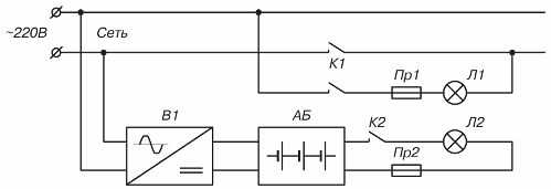
Rice. 1. Emergency lighting circuit using independent and main sources and separate lamps for main and emergency mode
The circuit contains: incandescent lamps (L1 — main, L2 — emergency), relay contacts (Kl, K2), fuses (Pr1, Pr2), rectifier (B1) and storage battery (AB).
In the main mode, the lamp L1 is turned on through the closed contact of the relay K1 from the network. The battery is connected to rectifier B1 and is in trickle charge mode.
When the mains voltage is switched off, the contacts K2 close automatically and a constant voltage is supplied to the lamp L2 from the storage battery.
When installing independent light sources, two power lines are laid: to the main and backup light source. All types of lamps are used for the main light source. For emergency work, incandescent lamps of lower wattage than lamps for basic lighting are usually used.
Use of one light source (incandescent lamps) for main and emergency mode
In cases where only incandescent lamps are used as lighting sources, and in emergency mode the lighting must remain unchanged, one source is used as the main and emergency. Such systems provide a transition from normal to emergency mode without flashing lamps.
The operation of the system is explained by the diagram in fig. 2.
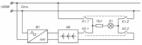
Rice. 2. Emergency lighting using a single source for main and emergency power modes with incandescent lamps only
The circuit contains: an incandescent lamp (L1 — main and emergency), relay contacts (K1, K2), fuse (Pr1), rectifier (B1) and battery (AB).
Lamp L1 in normal mode is powered by the mains through contacts K 1.1 and K 1.2. Rectifier B1 is permanently connected to the AC mains and keeps the battery in trickle charge mode. When the mains voltage is switched off, contacts K1.1 and K1.2 open and K2.1 and K2.2 close. Lamp L1 is powered by battery AB.In this case, the battery voltage is selected approximately equal to the effective value of the network voltage, as a rule, 220 V.
The advantage of such a scheme is the absence of additional lamps, and as a result, in emergency mode, the lighting remains unchanged, which is especially important, for example, in operating rooms.
Use of one light source (all types of lamps) for main and emergency mode
This class of emergency lighting systems provides constant power conditions to the lighting sources. The lamps, regardless of the mode, are powered by alternating voltage. The switching scheme of the lamp provides stabilization of the alternating voltage in case of overvoltages and voltage drops.
The operation of the system is explained by the diagram in fig. 3.
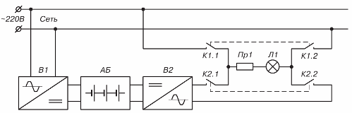
Rice. 3. An emergency lighting circuit using a single source for the main and emergency modes and lamps of all types
The circuit contains: an incandescent lamp (L1 — main and emergency), relay contacts (K1, K2), fuse (Pr1), rectifier (B1), storage battery (AB) and inverter (I1).
The circuit differs from the previous one by the presence of an inverter that converts the battery charge into alternating current. In conditions of unstable mains voltage, the lamp L1 is powered by the mains through a rectifier and an inverter. Thanks to this inclusion, flickering and premature failure of the lamp are excluded.
A separate group of this class consists of systems that include an automatic transfer switch (ATS). Scheme fig. 4 explains the operation of the ATS system.
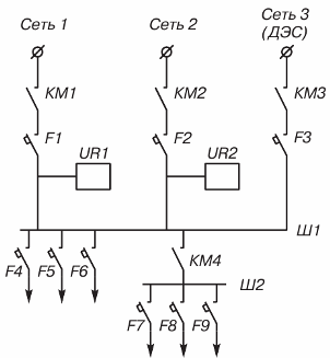
Rice. 4. Emergency lighting circuit containing automatic transfer switch
The circuit contains three voltage inputs — «Network 1», «Network 2», «Network 3», automatic current switches F1 — F9, controlled contacts KM1 — KMZ, mains voltage monitoring relay UR1, UR2, main power bus Ш1 , emergency power supply bus Sh2.
If there is a voltage at the "Network 1" input, the supply voltage is supplied through the closed contacts KM1 and the switch F1 to the bus Ш1. After switching off the voltage at the «Network 1» input, the contacts of KM1 open and KM2 close. Thus, the light sources connected to the Ш1 bus are powered by the "Network 2" input.
In the absence of voltage at both inputs "Network 1" and "Network 2", a diesel power plant (DPP) start signal is generated and the KMZ contact closes. Bus Ш1 is powered by input «Network 3». The voltage at the inputs is controlled by relays UR1, UR2, which track not only its absolute value, but also the dynamics of its change over time (frequent drops and surges of voltage). The latter excludes frequent switching and, as a result, flashing lights.
Lighting devices are connected to bus Ш1 through protective machines F4 — F6, and to bus Ш2 through machines F7 — F9, and Ш2 is connected to bus Ш1 through contacts KM4. When the power goes to DPP, some of the lighting devices automatically turn off the KM4 contact. The "Mains 2" source can be a separate phase of the mains or a separate power supply system, for example an inverter that converts battery charge to AC voltage. Such systems are designed and installed for lighting stadiums.
The indisputable advantage of emergency lighting systems of this class is the protection of light sources from the instability of the mains voltage and the predictable reliability of redundancy.
The considered emergency lighting systems provide practically all cases of redundant lighting. In addition, we note that at the same time you must take care of emergency power supply of equipment, the inoperability of which will lead to significant costs or a threat to human life.
The selection and design of a specific circuit should be done based on an analysis of the operating conditions, the backup time and the power of the energy users. When designing, it is necessary to additionally take into account the method of installation of power lines - cable or aerial.
The advantages of cable networks are that they are less susceptible to interruptions, which more often occur in aerial networks, for example, when transporting bulky cargo, falling trees, etc. The disadvantage is more time to find and fix network interruptions , which often occur during earthworks. The advantage of aerial networks is the short time to detect and eliminate network interruptions.
Without exception, all emergency lighting devices contain batteries and converters. Experience has shown that maintenance-free sealed batteries provide predictable reliability for a long service life.
Emergency lighting power systems are modular in design and are available in wall and floor mounts. The modules contain semiconductor converters, providing a battery conversion rate of over 90%.The modular design allows for configurable system configuration options and provides predictable reliability.
The power supply systems are equipped with alarm devices and control of the main functions (diagnostics of the state of the batteries and system operability), equipped with remote control.