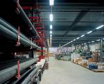
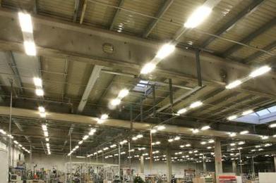
Design of electrical lighting for industrial premises
Project Represents an image of a future device or structure (system), presented in drawings, diagrams, tables, descriptions, created on the basis of calculations and comparison of options.
For large and complex industrial complexes, buildings and structures, the lighting installation project is developed in two stages: technical design and working drawings.
Technical design of electric lighting industrial premises
In the technical project, questions about the lighting and the electrical parts of the lighting installation are resolved, assignments are issued for the design of the power supply and basic construction solutions.
Working drawings of the production of electric lighting premises
 Working drawings are developed based on an approved technical project.
The development of a technical project or working drawings must be carried out in accordance with the environmental conditions of the premises, in full compliance with them PUE the groups and categories of the environment must be established data on the power sources of the lighting installation. When designing, it is recommended to study in detail the technological process of the illuminated enterprise and to know the nature of the visual work carried out in the premises.
In the plans of the power network, the construction part of the buildings is shown in a simplified way, panels are shown that show the number and installed power, network lines are applied, indicating brands and sections of cables and wires. In the plans of the main rooms, the places for placing lamps and shields are outlined fragmentarily. Luminaires, shields and various equipment are calculated according to plans and a table of indicators.
 Plan and section drawings contain basic information about lighting solutions and the electrical part of lighting installations.
When developing plans, it is necessary to use a set of symbols and requirements for applying inscriptions and numbers specified in GOST 21-614-88.
Luminaires, rack points, group screens, step-down transformers, power and group networks, switches, plug sockets apply to plans, room names, standardized lighting from general lighting, fire class and explosive areas, types, installation height of lighting fixtures and lamp power, wiring methods and cross-sections of wires and cables of lighting networks. Binding dimensions of places for installing lamps, shields, markings of places for laying lighting networks are indicated in cases where it is necessary to accurately fix these places.
 When designing buildings, a number of rooms of which have the same lighting solutions: lamps, lighting network and other identical elements - it is recommended that all solutions apply only to one room, for others they make a corresponding reference to it. Only the entrances to such premises are shown on the general floor plan. Floor plans of all rooms are drawn to a scale of 1:100 or 1:200.
In addition to plan drawings and sections of lighted rooms with attached lighting schemes, project documentation includes: customized specifications for electrical equipment and materials; construction buildings; remote control schematics or other electrical schematics, atypical assembly drawings.
Supplies and group networks on floor plans are applied more -thick lines from the construction elements of buildings and equipment, the number of wires in group lines is indicated by the number of serrations applied at an angle of 45 ° to network lines.
The common designation of the groups is necessary to ensure uniform loading of the phases. The connection phases are indicated on the plates without serial numbering of the groups. Plans indicate terminal data, grid voltages, symbol references, grounding information.
 Electric lighting is divided into working, emergency, evacuation (emergency lighting for evacuation), security. If necessary, some of the lighting fixtures of one or another type of lighting can be used for standby lighting (off-hour lighting).Artificial lighting is designed in two systems: general and combined, when local lighting (illumination of workplaces) is added to the general lighting.
Work lighting must be arranged in all premises of buildings, as well as in areas of the territory where work is carried out, vehicles move.
Calculation of electric lighting
The calculation of the lighting installation consists of two parts: lighting and electricity.
The lighting part contains: selection of light sources, standardized lighting, type and lighting system, type of lamps, safety factors and additional lighting; calculation of the placement of the lighting fixtures (determining the height of the suspension, the distance from the walls and between the lighting fixtures, the number of lighting fixtures), the luminous flux and the power of the lamp.
Appointment of lighting calculations
Lighting calculations allow you to do the following:
a) determine the number and unit power of the light sources of the lighting installation, which provides the necessary lighting in the room (on the work surface);
b) for an existing (designed) lighting installation, calculate the illuminance at each point on the surface of the illuminated room;
c) determine the quality indicators of the lighting installation (pulsation coefficient, cylindrical illuminance, glare and discomfort indicators).
The basic calculation of lighting illuminance consists in solving problems according to points a) and b) above. For this purpose apply two methods of calculating electric lighting: a method of utilizing the light flux and point method.
Classification of lighting engineering methods for lighting calculation
Method of using luminous flux It is used to calculate the total uniform illumination of horizontal surfaces, mainly to calculate the luminous flux of the light source (s). This method also makes it possible to calculate the average illuminance of a horizontal surface, taking into account all the fluxes falling on it, both direct and reflected. Not applicable for uneven placement of lighting fixtures, calculation of illuminance at characteristic points on both non-horizontal and horizontal surfaces.
A simplified form of the luminous flux utilization factor method is the power density per unit illuminated area method. This method is used for approximate calculations of total uniform illuminance. The maximum error in the calculation using the power density method is ± 20%.
 The point method of calculating lighting allows you to determine the illumination at any point on the surface of the illuminated room for any uniform or uneven placement of lamps. It is often used as a verification method to calculate illuminance at characteristic points on a surface. Using the point method, you can analyze the distribution of illumination throughout the room, determine the minimum illumination not only on a horizontal, but also on an inclined surface, and calculate emergency and local lighting.
The main disadvantage of the point calculation method is the neglect of the reflected light flux from the walls, ceiling and working surface of the room.
In cases where none of the above methods can be applied, for example, when calculating uneven illumination of a room with significant reflective properties of walls, ceiling and work surface, then both methods are used, acting in a combined manner.
For information on how to correctly calculate electric lighting, see here: Lighting calculation methods.
Electrical calculation of lighting
The electrical part of the project contains: selection of places for the main and group shields, the route of the network and power supply and lighting control circuits, the type of wiring and the method of laying it; calculation of the lighting network for the permissible voltage loss, followed by a cross-section check for continuous current and mechanical strength, protection of the lighting network; recommendations for the installation of the lighting installation; measures to protect against electric shock.