Schemes for remote control of outdoor lighting
 Remote control schemes for outdoor lighting used in modern projects (see the schemes below in Fig. 1 — 6) provide:
-
centralized lighting control from one point separately for each site,
-
control of the position of the magnetic starters,
-
local lighting control of individual objects with common centralized control,
-
repair of the disconnection of the external lighting from the power point,
-
the possibility of turning off the working lighting of objects in the controlled area from the central control panel for turning off the lighting,
-
partial switching off of the working lighting of a separate row of objects from the control cabinet.
Remote control is carried out by PM magnetic starters installed on the power lines of objects for outdoor lighting. The magnetic starters are automatically controlled from the control cabinets using the photo relay on the AO outdoor lighting control device.Manual remote control is possible via switches B in the control circuit by selecting the mode with the PU control mode switch.
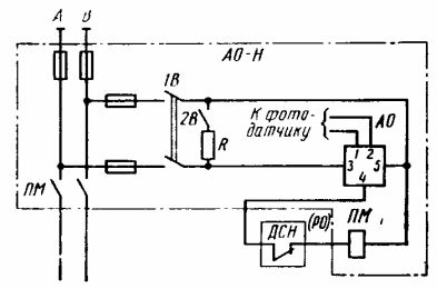
Rice. 1. Schematic diagram of lighting control circuits
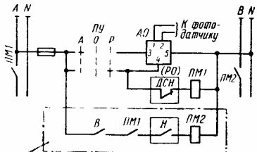
Rice. 2. Schematic diagram of lighting control circuits
Centralized shutdown of outdoor lighting is achieved by introducing a centralized shutdown relay RO in the control circuits of the block contact of the centralized stop panel or the block contact of the SDS double voltage drop relay installed in the relay cabinets.
The place to install the centralized shutdown of outdoor lighting consoles is determined by the project.
Facilities are divided into groups of emergency and working lighting for each controlled area with a specific design in accordance with the present instructions.
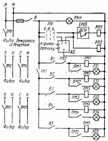
Rice. 3. Schematic diagram of lighting control circuits for up to five objects: RP1, RP2 — intermediate relay, LCN — supply voltage control lamp
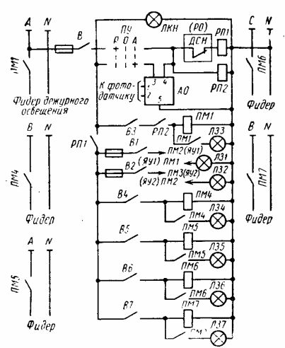
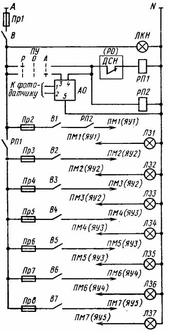
Rice. 4. Schematic diagram of lighting control schemes for up to seven objects when placing the NU or SHU control equipment in the control room
Remote control networks for outdoor lighting should be carried out with control cables laid in the ground or suspended on a cable along overhead line supports. Remote control networks are calculated based on the fact that for reliable operation of magnetic starters, the voltage loss in the network should not exceed 15% at the time of switching on.
When used in circuits of magnetic starters with large inrush currents, as well as large distances between the external lighting control point and the power supply points, an intermediate relay is introduced into the remote control circuit. In this case, the cross-section of the cable is selected according to the inrush current of this relay. It is recommended to use complete control devices such as power cabinets for outdoor lighting: control boxes and control cabinets. Electrical boxes and cabinets for outdoor lighting are installed in the subscriber section of transformer substations.
The centralization of lighting control is often carried out according to cascade schemes, in which the control of the sections of the distribution lines of the outdoor lighting network is carried out by connecting the contactor coil of the second section to the line of the first, the contactor coil of the third section to the line of the second etc. The number of sections should not exceed 10. In this case, the controlled direction of the cascade is created by sequentially switching on the sections, where the beginning of the first and the end of the last sections of the cascade are brought to the station for controlling and monitoring the state of the cascade.
Rice. 5. Schematic diagram of lighting control schemes for up to seven sites when placing NU or SHU control equipment at substations
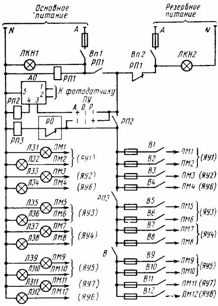
Rice. 6. Schematic diagram of lighting control schemes for up to 12 sites when placing substation control equipment
The remote control of outdoor lighting must be carried out according to a light calendar and a schedule for turning on and off installations for a populated place, according to the hours of operation of the lighting installations on a monthly basis for populated places located at different geographical latitudes, which can be used for planning electricity consumption.
Deviations from the schedule for turning on and off the installations, drawn up in clear weather, due to unfavorable weather conditions, are allowed for no more than 15 minutes, i.e. the total daily increase in the operating time of the installations is 30 minutes (15 minutes in the evening and 15 minutes in the morning).
It is recommended to clarify the time of switching on or off the installations, using photoelectric automatic devices of types, etc., in the control rooms adapted to the specified range of illumination.
Photo sensors must be installed in accordance with the instructions for their use. The general requirement is to orient the photosensor to the north so that direct sunlight does not fall on it during the day. Illumination of the photosensor from external light sources — lamps, projectors, etc. — must also be turned off.
See also: Outdoor lighting management for industrial enterprises