Switching circuits for gas discharge lamps
Artificial light sources that use an electric discharge of a gas medium in mercury vapor to generate light waves are called gas-discharge mercury lamps.
The gas pumped into the cylinder can be at low, medium or high pressure. Low pressure is used in lamp designs:
-
linear fluorescent;
-
compact energy saving:
-
bactericidal;
-
quartz.
High pressure is used in lamps:
-
mercury arc phosphorous (DRL);
-
metallic mercury with radioactive additives (DRI) of metal halides;
-
arc sodium tubular (DNaT);
-
sodium arc mirror (DNaZ).
They are installed in those places where it is necessary to illuminate large areas with low energy consumption.
DRL lamp
Design features
The device of a lamp using four electrodes is schematically shown in the photo.
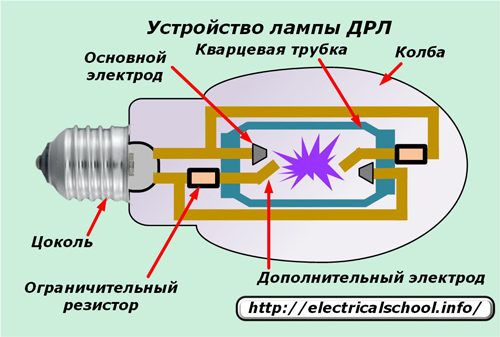
Its base, like conventional models, is used to connect to the contacts when it is screwed into the chuck. The glass bulb hermetically protects all internal elements from external influences. It is filled with nitrogen and contains:
-
quartz burner;
-
electrical wires from the base contacts;
-
two current-limiting resistors built into the circuit of additional electrodes
-
the phosphor layer.
The burner is made in the form of a sealed quartz glass tube with injected argon, in which are placed:
-
two pairs of electrodes — main and additional, located at opposite ends of the flask;
-
a small drop of mercury.
Argon — a chemical element that belongs to the inert gases. It is obtained in the process of air separation with deep cooling followed by rectification. Argon is a colorless, odorless monoatomic gas, density 1.78 kg / m3, tboil = –186 ° C. Argon is used as an inert medium in metallurgical and chemical processes, in welding technology (see electric arc welding), as well as in signal, advertising and other lamps that give a bluish light.
The principle of operation of DRL lamps
The DRL light source is an electric arc discharge in an argon atmosphere flowing between electrodes in a quartz tube. This happens under the action of a voltage applied to the lamp in two stages:
1. Initially, a glow discharge begins between the closely located main and ignition electrodes due to the movement of free electrons and positively charged ions;
2. The formation of a large number of charge carriers in the torch cavity leads to the rapid breakdown of the nitrogen medium and the formation of an arc through the main electrodes.
Stabilization of the starting mode (electric current of the arc and light) takes about 10-15 minutes. During this period, the DRL creates loads that significantly exceed the rated mode currents. To limit them, apply ballast — suffocation.
Rainbow radiation in mercury vapor has a blue and violet hue and is accompanied by powerful ultraviolet radiation. It passes through the phosphor, mixes with the spectrum it forms and creates a bright light that is close to white.
The DRL is sensitive to the quality of the supply voltage and when it drops to 180 volts, it goes out and does not light up.
During arc discharge a high temperature is created, which is transferred to the entire structure. This affects the quality of the contacts in the socket and causes heating of the connected wires, which are therefore only used with heat-resistant insulation.
During the operation of the lamp, the gas pressure in the burner increases significantly and complicates the conditions for the destruction of the medium, which requires an increase in the applied voltage. If the power is off and applied, the lamp will not start immediately: it needs to cool down.
DRL lamp connection diagram
The four-electrode mercury lamp is switched on by means of a choke and fuse.
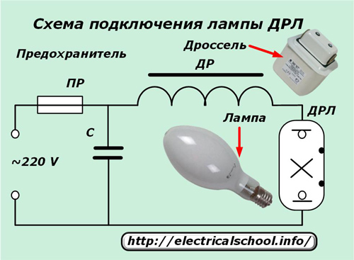
A fusible link protects the circuit from possible short circuits, and the choke limits the current flowing through the middle of the quartz tube. The inductive resistance of the choke is selected according to the power of the lighting fixture. Turning on the lamp under voltage without a choke causes it to burn out quickly.
A capacitor included in the circuit compensates for the reactive component introduced by the inductance.
DRI lamp
Design features
The internal structure of the DRI lamp is very similar to that used by the DRL.
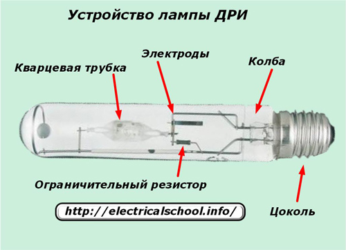
But its burner contains a certain amount of additives from the hapogenides of the metals indium, sodium, thallium or some others. They allow you to increase the light emission to 70-95 lm / W and more with good color.
The flask is made in the form of a cylinder or ellipse shown in the figure below.
The material of the burner can be quartz glass or ceramic, which has better operational properties: less darkening and longer operational life.
The ball-shaped burner used in the modern design increases the light output and brightness of the source.
Operating principle
The basic processes taking place during the production of light from DRI and DRL lamps are the same. The difference lies in the ignition scheme. DRI cannot be started from the applied mains voltage. This value is not enough for her.
To create an arc inside the torch, a high voltage pulse must be applied to the interelectrode space. His education was entrusted to the IZU — a pulse ignition device.
How IZU works
The principle of operation of the device for creating a high-voltage pulse can be conditionally represented by a simplified schematic diagram.
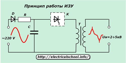
The operating supply voltage is applied to the input of the circuit. Diode D, resistor R and capacitor C create a capacitor charging current. At the end of charging, a current pulse is supplied through the capacitor through the open thyristor switch in the winding of the connected transformer T.
A high voltage pulse up to 2-5 kV is generated in the output winding of the step-up transformer. It enters the contacts of the lamp and creates an arc discharge of the gaseous medium, which provides a glow.
DRI type lamp connection diagrams
IZU devices are produced for gas discharge lamps of two modifications: with two or three wires. For each of them, its own connection diagram is created.It is provided directly on the block housing.
When using a two-pin device, the power phase is connected through the choke to the central contact of the lamp base and simultaneously to the corresponding output of the IZU.
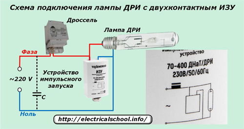
The neutral wire is connected to the side contact of the base and its IZU terminal.
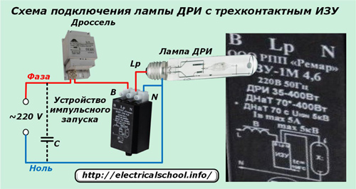
For a three-pin device, the neutral connection scheme remains the same and the phase supply after the choke changes. It is connected through the two remaining outputs to the IZU, as shown in the photo below: the input to the device is through the terminal «B», and the output to the central contact of the base through — «Lp».
Thus, the composition of the control device (ballast) for mercury lamps with emitting additives is mandatory:
-
throttle;
-
pulse charger.
The capacitor compensating the reactive power value can be included in the control device. Its inclusion determines the general reduction of energy consumption by the lighting device and the extension of the life of the lamp with a correctly selected capacity value.
Approximately its value of 35 μF corresponds to lamps with a power of 250 W and 45 - 400 W. When the capacity is too high, resonance occurs in the circuit, which is manifested by the "blinking" of the light of the lamp.
The presence of high-voltage pulses in a working lamp determines the use of extremely high-voltage wires in the connection circuit with a minimum length between the ballast and the lamp, no more than 1-1.5 m.
DRIZ lamp
This is a version of the DRI lamp described above that has a partially mirrored coating inside the bulb to reflect the light, which forms a directional beam of rays.It allows you to focus the radiation on the illuminated object and reduce light losses resulting from multiple reflections.
HPS lamp
Design features
Inside the bulb of this gas-discharge lamp, instead of mercury, sodium vapor is used, located in an environment of inert gases: neon, xenon or others, or their mixtures. For this reason they are called "sodium".
Due to this modification of the device, the designers were able to give them the greatest efficiency of operation, which reaches 150 lm / W.
The principle of action of DNaT and DRI is the same. Therefore, their connection diagrams are the same, and if the characteristics of the ballast match the parameters of the lamps, they can be used to ignite the arc in both designs.
Manufacturers of metal halide and sodium lamps produce ballasts for specific product types and ship them in a single housing. These ballasts are fully functional and ready to go.
Wiring diagrams for DNaT type lamps
In some cases, HPS ballast design may differ from the above DRI start-up schemes and be performed according to one of the three schemes below.
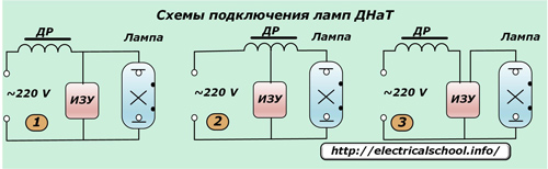
In the first case, the IZU is connected in parallel to the contacts of the lamp. After the ignition of the arc inside the burner, the operating current does not pass through the lamp (see IZU circuit diagram), which saves electricity consumption. In this case, the choke is affected by high voltage pulses. It is therefore constructed with reinforced insulation to protect against ignition pulses.
Therefore, the parallel connection scheme is used with low-power lamps and an ignition pulse of up to two kilovolts.
In the second scheme, IZU is used, which works without a pulse transformer, and high-voltage pulses are generated by a choke of a special design, which has a tap for connecting to the lamp socket. The insulation of the winding of this inductor also increases: it is exposed to high voltage.
In the third case, the method of connecting the choke, IZU and the lamp contact in series is used. Here, the high voltage pulse from the IZU does not go to the choke, and the insulation of its windings does not require amplification.
The disadvantage of this circuit is that the IZU consumes an increased current, due to which its additional heating occurs. This necessitates an increase in the dimensions of the structure, which exceed the dimensions of the previous schemes.
This third design option is most often used for the operation of HPS lamps.
All schemes can be used reactive power compensation capacitor connection as shown in the DRI lamp connection diagrams.
The listed circuits for turning on high-pressure lamps using a gas discharge for lighting have a number of disadvantages:
-
underrated glow resource;
-
depending on the quality of the supply voltage;
-
stroboscopic effect;
-
throttle and ballast noise;
-
increased electricity consumption.
Most of these drawbacks are overcome by using electronic trigger devices (ECG).
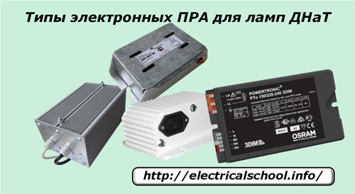
They allow not only to save up to 30% of electricity, but also have the ability to smoothly control the lighting. However, the price of such devices is still quite high.