Dialux program for calculating and designing lighting
 Dialux is one of the most functional computer programs for performing lighting calculations and engineering design of indoor and outdoor lighting. It has been developed and improved to this day since 1994 by the German company DIAL GmbH, while it is distributed and updated for free. A group of twenty programmers constantly maintain and improve the product.
Dialux software is an effective tool for solving complex problems in calculating both natural and artificial lighting in various outdoor and indoor scenes, streets, roads, workplaces, offices, emergency systems, sports fields and many others. Dialux is useful for designers, electricians and designers alike to carry out their work in accordance with lighting regulations. The program interface supports many languages, including Russian.
Dialux is one of the most widely used lighting calculation tools of its kind today. Many global lighting manufacturers create their own databases of their luminaires for Dialux.The program is supported by over 100 partners. New catalogs can be linked directly from the program, thanks to which the developer gets the widest selection of products.
According to the initially specified conditions: the number of lighting fixtures, their type, location, the Dialux program is able to perform various complex lighting calculations, in which all factors related to furniture, various interior elements, room geometry, color and texture of all surfaces will be taken into account. The program allows you to perform calculations for all types of lighting, KEO, brightness, gloss, shadows and daylight. The utility takes into account weather conditions, geographic location of an object, shadows from surrounding objects and buildings.
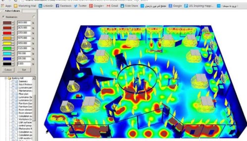
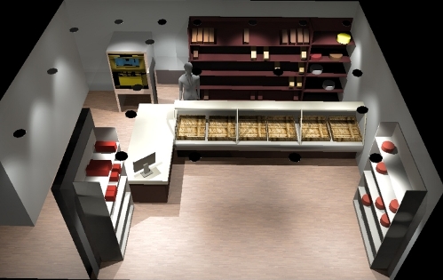
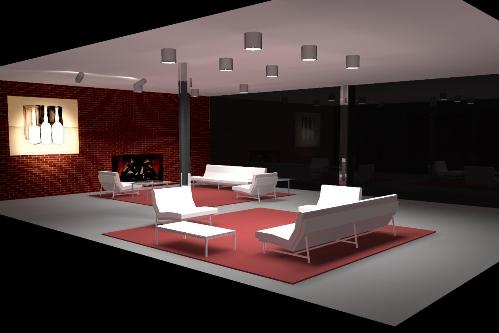
Based on the results of the calculation, the program builds graphs, isolines and tables of the lighting distribution, generates statements about the lighting fixtures with their passport data. The distribution of illumination on the viewed surface is graphically displayed and a photorealistic three-dimensional drawing of the room is built, thanks to the integrated POV-Ray visualizer.
It is possible to create videos of the lighting project. The tables will show the energy consumption of the designed system and its optimization. The library of objects is initially extensive, but you can create them yourself using modeling tools such as boolean operations, extrusion, etc. This way you can create your own lights, windows, doors, furniture, etc.
For each area, you can simulate a variety of lighting effects with bright reflection, transparency, enhanced textures according to the specified parameters. The modernized core of the program makes the rendering of scenes faster and the colors more natural and saturated.
The program allows you to create visual video presentations with a mirror and transparent effect. Of course, the normal operation of the program requires good system resources, a processor of at least Pentium IV class and at least 1 GB of RAM.
Novice users can use the "DIALux Light Wizard" which is included in the software package and is designed to guide you through the steps to get accurate calculations.
The program fully supports all modern national and international standards and European measurement units. You can export / import objects and data to and from any CAD program in .dwg and .dxf formats. The presence of prompts and intuitive control greatly facilitate working with the program.
The DIALux software greatly simplifies the process of calculating a general system for artificial lighting of premises with a three-dimensional visualization of design solutions. The program is interactive: it allows the user to move in a lit, calculated interior.
Lighting calculation and design of lighting installations in DIALux
Program interface:

In the title of the window there is a command line, below there are buttons and toolbars for quick execution of DIALux commands and functions.
To the left of the button panel there are buttons "select surfaces and room elements", "enable or disable the selection of windows, doors and computational surfaces", "enable or disable the selection of furniture", "enable and disable the selection of individual lamps «,» enable or disable the selection of lighting groups «,» enable or disable the selection of calculated points ".
On the right there are buttons that can be used to control the model: "select objects", "zoom in and out", "rotate the view", "shift the view", "move around the scene". All these buttons allow you to quickly work with the model.
The rest of the window is divided into 4 main work areas. In the upper left corner is the Inspector, which allows you to set parameters for objects in the model. In the lower left corner is Explorer and the Tree Project window. The rest is reserved for the CAD window. These four working areas allow efficient and clear planning of the lighting installation.
In each of these areas, you can call a specific software function and process the objects accordingly. The CAD window is used for interactive lighting planning. In it, you can graphically, using the mouse, move around the scene, rotate, zoom in (zoom in), move a room, a street scene or a standard road.
Also a big plus of this window is the ability to view the model from all sides. The function to zoom in/out of the 3D scene model is available with the mouse wheel.
The project tree allows you to quickly work with lighting planning elements.Each of the elements can be marked and modified and its properties can be viewed in the Inspector.
The researcher directly opens the stages of work necessary for planning. It serves as a "red thread" and guides the user quickly to the goal. The inspector allows you to view the properties of each marked object in the CAD view or in the project tree. Some values can be changed here.
1. The first step in creating a project for a lighting installation is to create a model of the room in accordance with all the exact geometric dimensions, in addition, at this stage the values of the reflection coefficients of the ceiling, walls and floor are also entered. The resulting model can be viewed in different views: top view, side view, front view and 3D display.
2. The second stage is the creation of models of furniture, as well as the creation of a model of the front door. Furniture - wood is divided into three subdirectories:
-
Files of ready-made furniture or self-made furniture. Here you can also store furniture from other manufacturers in the form of SAT files.
-
Standard geometric bodies such as square, prism, etc.
From this, you can easily compose new objects—such as windows, doors, virtual computing surfaces, and floor elements for an outdoor scene. Objects with special properties. The program provides the ability to move existing objects inside or outside the room, rotate and mark using a special context menu.
3. The third step is to choose the texture of the room's surfaces and furniture, using wood textures. At this stage of the design, the choice of color, material, reflection coefficients of the furniture surfaces is made.
The texture tree allows, in the same way as placing furniture in a room, to change the characteristics of the planes. Here are the given textures (surface painting), RAL-colors, you can also contain your own textures here. In case the texture is applied incorrectly, it can be corrected.
4. The fourth step is the selection of lighting fixtures. There is a separate tree structure for this. The user has the opportunity to choose lighting fixtures from different manufacturers — plug-ins with which he regularly works. These lighting fixtures can be deleted and saved in «Own data bank».
With the release of DIALux 3 and subsequent versions of the program, the demo luminaires are entered into their own database. They can be removed and replaced with genuine fixtures from the manufacturers. After the geometry of the room is processed and all data is entered, the calculation begins.
There is another tree to choose from and view the results. Results marked in red on the symbol sheet are immediately available to the user. To get results without a red check mark, you must first do a calculation. All results can be seen on the screen.