Selection of cable and wire cross-section: by heating, by current, by voltage loss
Cross-section of wires and cables is determined based on permissible heating, taking into account normal and emergency modes, as well as the uneven distribution of currents between individual lines, since heating changes the physical properties of the wire, increases its resistance, increases the useless consumption of electrical energy to heat conductive parts and shorten the life of the insulation. Excessive heat is dangerous to the insulation and contact connections and can lead to fire and explosion.
Selection of cable and cross-section of heating wire
The selection of the cross-section from the conditions of permissible heating is reduced to the use of the relevant tables of long-term permissible current loads Id, in which the conductors are heated to the maximum permissible temperature established by practice in order to prevent premature wear of the insulation, to ensure reliable contact at the connection points of the wire and to eliminate various emergency situations that occur at Id ≥ Ip, Ip — rated load current.
Intermittent intermittent loads when selecting a cable cross-section are recalculated to a reduced continuous current

where Ipv is the off-mode current of the receiver with the duration of the PV activation.
When choosing the cross-section of wires and cables, it should be taken into account that at the same heating temperature, the permissible current density of conductive wires with a larger cross-section should be smaller, since their cross-section increases to more -large the degree of growth of the cooling surface (see rice. 1). For this reason, to save non-ferrous metals, instead of one cable with a larger cross-section, two or more cables with a smaller cross-section are often chosen.
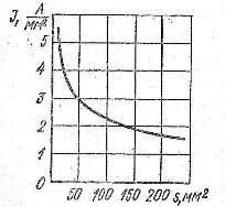
Figure 1. Graph of the dependence of the permissible current density on the cross-section of copper conductors in an outdoor three-core cable for a voltage of 6 kV with impregnated paper insulation, heated by current to a temperature of + 65 ° C at an air temperature of +25 «C.
 In the final selection of wires and cables from the condition of permissible heating according to the relevant tables, it is necessary to take into account not only the estimated current of the line, but also the method of its laying, the material of the wires and the ambient temperature.
Cable lines for voltages above 1000 V, selected according to the conditions of permissible long-current heating, are also checked for heating by short-circuit currents. In the event that the temperature of copper and aluminum conductors of cables with impregnated paper insulation with voltage up to 10 kV exceeds 200 ° C and cables for voltage 35-220 kV above 125 ° C, their cross-section increases accordingly.
The cross-section of wires and cables of internal power networks with a voltage of up to 1000 V is coordinated with the switching capabilities of linear protective devices — fuses and circuit breakers — so the inequality is justified Azd / Azc h, where kz — the multiple of the allowable long-term current of the wire to the nominal current or the current of the protective device Azs (from PUE). Failure to satisfy the above inequality forces the selected main section to be increased accordingly.
Selection of the cross-section of cables and wires for voltage loss
The cross-section of the cables and conductors selected by the heating conditions and consistent with the switching capabilities of the protective devices relative linear voltage loss must be checked.
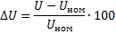
where U is the voltage of the source of electrical energy, Unom is the voltage at the connection point of the receiver.
The permissible deviation of the motor terminal voltage from the nominal voltage should not exceed ± 5%, and in some cases it can reach + 10%.
In lighting networks, the voltage drop for the most distant lamps of internal work lighting and projector installations of external lighting should not exceed 2.5% of the nominal voltage of the lamps, for lamps for external and emergency lighting — 5%, and in networks with voltage 12.,. 42V — 10%. A greater reduction in voltage leads to a significant decrease in the illumination of workplaces, causes a decrease in labor productivity and can lead to conditions in which the ignition of gas discharge lamps is not guaranteed. The highest voltage of the lamps, as a rule, should not exceed 105% of its nominal value.
An increase in the voltage of the internal power supply networks beyond what is provided for in the norms is not permissible, as it leads to a significant increase in the consumption of electrical energy, a decrease in the service life of power supply and lighting of electrical equipment, and sometimes to a decrease in the quality of products.
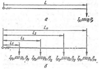
Rice. 2. Calculation of voltage loss in a three-phase three-way line when choosing the cross-section of cables and wires: a-with one load at the end of the line, b-with several distributed loads.
Checking the cross-section of the wires of a three-phase three-wire line with one load at its end (Fig. 2, a), characterized by the rated current Azp and power factor cos phi for the relative linear voltage loss, perform as follows:

where Unom is the nominal voltage of the network, V, Ro and Xo are the active and inductive resistance, respectively, of one kilometer of the line, selected from the reference tables, Ohm / km, Pp is the calculated active power of the load, kW; L is the length of the line, km.
For an unbranched main three-phase three-wire line of constant cross-section, carrying loads distributed along it with rated currents Azstr1, AzR2, ..., Azr and the corresponding power factors cos phi1, cos phi2, ..., cos phi distant from the power source at distances L1, L2, …, Ln (Fig. 2, b), the relative linear voltage loss to the farthest receiver:

where PRi active power — calculated i-th load remote from the power source at a distance L.
If the calculated relative voltage loss dU will turn out to be higher than the permissible norms, it is necessary to increase the selected section to ensure the normalized value of this value.
With small cross-sections of wires and cables, the inductive resistance Xo can be neglected, which greatly simplifies the corresponding calculations. in three-phase three-wire distribution networks of outdoor lighting, which differ in a significant length, you must pay attention to the correct inclusion of equidistant lighting fixtures, because otherwise voltage loss are unevenly distributed over the phases and can reach several tens of percent compared to the nominal voltage.
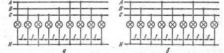
Schemes for turning on equidistant lighting fixtures for outdoor lighting: a — correct, b — incorrect
Selection of cable cross-section for economic current density
The selection of the cross-section of wires and cables, without taking into account economic factors, can lead to significant losses of electrical energy in the lines and a significant increase in operating costs.For this reason, the cross-section of wires of electrical networks with internal power supply of considerable length, as well as networks operating with a large number of hours of use of the maximum load -Tmax > 4000 h - must at least be responsible for a recommended economic current density that establishes the optimal ratio between capital costs and operating costs, which is defined as follows:

where Azr — nominal current of the line, without taking into account the increase in load in case of breakdowns and repairs, Jd — economic current density based on the repayment of capital costs within 8 — 10 years.
 Expected economic cross-section rounded to the nearest standard and, if it turns out to be more than 150 mm2, one cable line is replaced by two or more cables with a total cross-section corresponding to the economic one. Use low changing load cables with a cross-section of less than 50 mm2 Not recommended.
Cross-section of cables and wires with a voltage of up to 1000 V with the number of hours of use of the maximum load Tmax <4000 … 5000 h and all branches to receivers of the same voltage, electrical networks of lighting installations, temporary structures and structures with a short service life up to 3 — 5 years are not chosen according to the economic current density.
In three-phase four-pass networks, the cross-section of the neutral conductor is not calculated, but at least 50% of the cross-section selected for the main conductors is taken, and in networks supplying gas discharge lamps, which cause the appearance of higher current harmonics, the same as for the main wires.