Lighting for galleries and tunnels
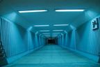 For lighting galleries and tunnels in as many light sources as NSapplied as incandescent lamps and gas discharge lamps (fluorescent lamps, low power high pressure gas discharge lamps).
In galleries and tunnels of conveyors with hydraulic dust removal (in sintering and processing plants, aluminum plants, etc.) it is preferable to use fluorescent lamps installed in lighting fixtures with a degree of protection 5'4 or AzP54.
In cases where the application of fluorescent lamps is not possible, for example in unheated galleries, with hydraulic dust removal, it is allowed to use lamps with incandescent lamps with heat-resistant glass or a lamp with a lower power for this type of lighting fixtures.
Luminaires should be located to provide illumination not only of the aisles between conveyors and conveyor belts, but also of areas below the conveyors for cleaning up spills, checking rolls, etc.As a rule, it is recommended to place the lighting fixtures along the axes of the passages between the conveyors in accordance with the figure.
The choice between voltage 12 and 40 V is determined by the accepted value of the voltage of portable lighting in the main workshops of the enterprise. When the mains voltage for general lighting for galleries and tunnels is 40 V, this voltage is also accepted for portable lighting.
Portable lighting sockets are installed: in galleries and tunnels of conveyors, cable tunnels — after 30-40 m (as a rule, in a block with a transformer), in water supply, heating tunnels, in tunnels of slurry pipes — at nodal points. Luminaires in conveyor galleries and tunnels are installed outside the conveyor area.
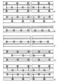
Rice. 1. Recommended layouts of lighting fixtures and laying of group network in galleries and tunnels
Given the episodic nature of visits to galleries and tunnels by service personnel and the small number of the latter, as well as the nature of work in them, the arrangement of emergency lighting is not required, although it is recommended for long repeated conveyor galleries without natural light and tunnels. The exception is the galleries with wires above 1 kV, where every second lighting fixture is intended for emergency lighting.
In tunnels and galleries without natural light, it must be possible to safely replace lamps and repair lighting installations powered by voltage 380/220 V with artificial lighting, which is achieved by appropriately connecting the lamps to the network, for example by distributing every third lamp or one of the rows for standby lighting in a multi-row arrangement.
When choosing the voltage for lighting fixtures for galleries and tunnels, the height of which, as a rule, does not exceed 2.5 m, the implementation of lighting installations for a voltage of 220 V is not excluded in some cases.
The large cost of cable production occurs when building a portable lighting network in extended structures such as galleries and tunnels. The reduction of cable consumption can be achieved by a rational power supply scheme of the contacts.
In galleries with live wires and cable tunnels, served by qualified personnel, whose general lighting is powered by a voltage of 220 V, it is recommended to supply portable lighting from the general lighting network, connected to the network from sockets for portable transformers or connect to the network for general lighting "transformer - socket", installed after 30 — 40 m. When the voltage of the network for general lighting is 40 V, it is recommended to connect the contacts to the same network.
In galleries with sufficient natural light and artificial lighting made with fluorescent lamps, it is permissible to completely refuse the installation of plugs for portable lighting, except for the nodal points of equipment installation.
Electrical wiring in galleries and tunnels is mainly carried out with cables on wire rope (wire rod). Heat-resistant cables and wires are used in high-temperature areas (sintering galleries, scaling tunnels, etc.).
In galleries and tunnels used as personnel passages between buildings and structures (galleries and conveyor tunnels, oil, etc.), electric lighting control it is necessary to provide devices installed in one place (Fig. 2, a).
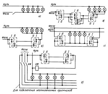
Rice. 2.Recommended lighting control schemes in galleries and tunnels. The designations of the «phase» and «zero» wires must be observed only for a mains voltage of 220 V
In locked galleries and tunnels visited from time to time by special personnel and not used as passages between buildings and structures for other personnel, the so-called corridor control scheme is used from two or more places; in this case, control devices are installed at each of the entrances through which there is access to the premises. Such structures include cable, heating, water supply galleries and tunnels, galleries with wires.
In fig. 2, b shows a scheme for controlling the corridor from two places, where single-pole switches for two directions without zero positions are used as control devices.
In fig. 2, d shows a diagram for three-phase lines with a significant load. In this case, the line is not controlled directly, but through magnetic switchinstalled on the line.
When calculating voltage loss according to the diagram in fig. 2, b the moment of loading is determined by the formula M = ∑P2λ, where P is the sum of the loads of all lamps of the line, kW; λ — the length of the line to the center of the load, m.
In fig. 2, c shows a control scheme for three or more locations. Single-pole switches for two directions without zero positions are used as control devices at the beginning and end of the line (similar to the diagram in Fig. 2, b), as intermediate devices - two-pole switches for two directions without zero positions.
When controlling not directly on a line, but through a magnetic starter (Fig. 2, e), the same control devices are used as for the circuit in Fig. 2, c.
Sometimes it is necessary in the case of corridor control schemes that part of the load on the line is not switched off (emergency lighting, plugs, etc.). In this case, it is recommended to operate according to the diagram in fig. 2d using a transit circuit. The same scheme is recommended for separate lighting control along the tunnel sections between the entrances.
When calculating the voltage loss lines, the load moment M is determined by the formula M = ∑P3λ.
Used materials from the book Obolentsev Yu. B. Electric lighting of general industrial premises.