Power circuits for lighting installations
 Emergency lighting outages cause material damage caused by reduced production and sometimes damage to equipment and raw materials. In some cases, this is exacerbated by the danger of fire, explosion, individual and even mass injury that can result from inadvertent or improper actions by personnel in the dark. Therefore, much attention is paid to the issue of power supply reliability for lighting installations.
according to the requirements PUE emergency lighting fixtures, in order to continue working, must be connected to an independent power source, that is, to a power source that maintains voltage when it disappears from other sources of this object.
Independent power supplies are, for example, two bus sections substation (TP), each of which receives power from a transformer, which in turn is powered by an independent source (for example, the transformers are connected to different generators of a power plant).In this case, the bus sections of the substation must not be connected to each other or the connection between them must be broken automatically if one of them fails.
 Accumulator batteries and diesel generators are also independent sources of energy. These energy sources are used to power emergency lighting in cases where there is no other, more economical way to provide an independent power supply.
It is allowed to power emergency lighting fixtures from the working lighting network with automatic switching to power from an independent source in case of emergency extinguishing of the working lighting.
In industrial buildings without windows and lanterns, emergency lighting must be supplied from an independent source for both continued work and evacuation. In such rooms, the work and emergency lighting networks must come from different power sources; it is not allowed to use power networks to power general working or emergency lighting.
An independent power source for emergency evacuation lighting is also required in buildings where a large crowd of people is possible: theaters, cinemas, clubs, metro stations, stations, museums, etc.
In other cases, the emergency lighting supply for evacuation may not be independent, but where possible, the maximum reliability of the emergency lighting supply should be ensured.
The reliability of the lighting installation is largely determined by the adopted power scheme.When choosing a circuit, the required degree of reliability, the required level and constancy of the voltage at the light sources, the ease of use and the cost-effectiveness of the installation are taken into account.
If the facility has one substation with one transformer (Fig. 1), it is recommended to supply different loads (power, work and emergency lighting) with independent power lines from the low voltage buses of the transformer substation. In this case, extinguishing all lighting is possible only in case of transformer failure, which is practically rare.
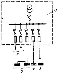
Fig. 1. The power circuit of the lighting installation from a single-transformer substation: 1 — transformer substation, 2 — electrical load, 3 — working lighting, 4 — emergency lighting.
It is permitted to supply electrical and lighting loads to small, low-critical buildings with one line from the transformer substation. At the same time, the separation of networks for energy load, working and emergency lighting is mandatory and must start from the entrance to the building.
In fig. 2 shows the power supply scheme of the lighting installation in the presence of two single-transformer substations of the facility. In this case, the power supply for working and emergency lighting of buildings (or sections of the same building), as a rule, is produced from different substations.
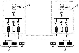
Rice. 2. Electric circuit of the lighting installation from two single-transformer substations: 1 — transformer substation, 2 — power load, 3 — working lighting, 4 — emergency lighting.
Such a scheme is more reliable than the previous one, because when one transformer fails, one of the types of lighting continues to work, powered by another substation.
If the transformers are independently fed, then both transformer substations are considered independent feeds. The power supply from two transformer substations allows to improve the quality of the lighting by choosing to supply the working lighting to one of them, the bus voltage of which is more constant.
A similar circuit disassembled above (Fig. 2) is the widely used circuit for powering lighting from a two-transformer substation.
The low-voltage busbars of two-transformer TPs are divided into two sections according to the number of transformers. A section switch is installed between the sections, which allows you to connect the two sections into one. Work and emergency lights are powered by different sections. If the TP transformers are supplied by different generators of the power plant, they are independent sources.
In the event of an accident with one transformer of a two-transformer substation, it is automatically tripped and at the same time the section switch is closed, this is called an automatic transfer switch, and then both sections remain energized, receiving power from one operating overload transformer . In this case, the working and emergency lighting remain on.
In a number of industrial enterprises, the power supply of electrical loads is successfully used according to the transformer-bus block diagram (Fig. 3).
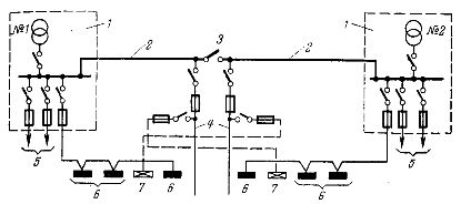
Rice. 3. The power circuit of the lighting installation with the transformer-main device system.1 — transformer substation, 2 — main line, 3 — jumper disconnector between main lines, 4 — secondary lines, 5 — power load, 6 — working lighting, 7 — emergency lighting.
In such a scheme, the busbars of the low-voltage switchboards of single-transformer transformer substations located in the workshop seem to be extended, forming extended power supply lines-the main highways (constructively executed in the form of trunk bus channels).
Between the main highways of two adjacent transformer substations are established disconnectors, playing the role of sectional switches of the two-transformer TP circuit. Secondary lines with a smaller section (busbars).
A small number of line switches are stored on the low voltage boards of the transformer substation, one of which can be used to power the work lighting of the workshop section adjacent to the transformer substation. Emergency lighting of the same section of the workshop, unlike the diagram in fig. 2 can be connected to the secondary line of an adjacent transformer substation.
The disadvantage of this scheme compared to the scheme shown in fig. 2, is the worse quality of the voltage supplied to the emergency lighting (large fluctuations caused by starting electric motors and large voltage losses in the supply networks). If the neighboring transformers are supplied by different generators of the power plant, they are independent sources and then the circuit will have high reliability.
In fig.1 — 3 group panels with working and emergency lighting are connected directly to the power lines coming out of the transformer substations. In practice, it is often necessary to install intermediate backbone shields (MCBs).
The need to install main screens is caused by the desire to reduce the cross-sections of the supply lines, to create the possibility of disconnecting individual lines for repair and to reduce the number of lines leaving the low-voltage switchboard of the transformer substation.