DALI lighting control system
Lighting control systems
 Appointment of integrated lighting control systems, this is primarily an increase in energy efficiency, an increase in home comfort, and an improvement in the operational characteristics of industrial buildings. Research into simple lighting control systems based on analog sensors has shown that such systems can effectively reduce energy consumption. Expanded lighting control technologies provide even greater savings, have additional capabilities and have a number of advantages over simple control methods.
The lighting control system market is mainly represented by manufacturers of components (control devices, switches, ballasts) rather than technical solutions. Often these components do not provide the required functionality as part of the systems. This applies primarily to lighting control... This should also include the complexity of wiring, the difficulty of installing daylight control equipment.These circumstances lead to malfunctions of lighting systems, consumer complaints. These are the common disadvantages of analog lighting control systems.
In the last 15 years, all lighting control systems were analog... The device of more or less complex systems differed little from each other and was built according to the classic automation scheme. The basis of the system, as a rule, is a controller, to which various sensors are connected on one side, and actuators on the other. The connection between the sensors and the controller is mostly analog, the same connection is between the executive mechanisms and the controller.
The main purpose of such devices is efficient energy management. Commissioning and configuring such systems is quite complex and even more difficult if the system includes several of these analog lighting controllers.
Transition to digital systems
In order to overcome these shortcomings and difficulties, lighting system manufacturing companies began to master the production of digital lighting control systems... The main advantage of digital systems over analog ones is communication, communication between individual devices integrated into a system.
 Digital systems do not require separate wires for communication; most digital devices can use power cables to transfer information. One of the latest developments in the field of lighting management is DALI (Digitally Addressable Lighting Interface)... It is this interface that allows, by integrating microcontrollers in lighting ballasts, to take the first bold step into the digital world.
Intelligent DALI interface
The DALI interface was developed in 1999. It replaced the DSI (Digital Serial Interface) control system. Since DALI is designed for lighting control, leading manufacturers of electronic ballasts, mainly Osram, Philips, Tridonic, Trilux, Helvar, took part in the development of the system.
Lighting control can be considered as a kind of art, which can be required when lighting a theater stage, industrial premises, street and finally residential areas. Recently, the "smart home" has become more and more popular and widespread. Therefore, the lighting control system is one of its constituent parts and, ensuring the comfort of the home, it is not the last place. The DALI system is almost ideal as such a part.
The choice of parameters for each control system is dictated by the task to be performed with its help. It is important that the new system can be easily integrated into the existing one, merge with it, work together, not instead of it. In terms of integration into other control systems, the DALI system is quite simple and economical.
The DALI-based lighting control system can be easily integrated into various building automation systems such as LON, BACNet, KNX / EIB. For such a combination, many companies produce KNX-DALI and LON-DALI gateways. This union allows you to reduce the time to install the system, make it cheaper, and also more flexible in management.
The protocol standard and the DALI hardware are intended only for lighting control, which indicates a narrow specialization of this system. Therefore, the overall system proved to be highly efficient and inexpensive. The connection of devices using the DALI protocol is shown in Figure 1.
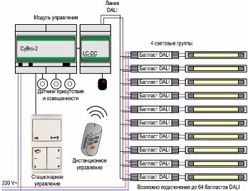
Figure 1. Block diagram of the DALI system.
Data transmission and system programming
The DALI system is currently standardized according to the IEC 60929 standard. As shown in Figure 1, the communication between the DALI controller and the individual devices takes place over a two-wire line. The DALI line is a two-way interface that allows the transfer of information both from the controller to peripherals and vice versa.
An extremely low DC voltage of 22.5V is used for data transmission. In this case, the polarity of connecting the line to different devices does not matter, and the line itself is protected from the voltage of the lighting network. The immunity of the line to interference is such that it can be located in a power cable and even just use free conductors of this cable.
 The DALI network bus does not have a central processor, i.e. decentralized. This organization allows you to connect to this network any device designed to work with the DALI bus. Such devices, as a rule, have a built-in non-volatile memory that allows storage of various information. First of all, this is the address of the device, information about the device and the status of the lamps connected to it, as well as whole sets of commands, also called scripts.
Programming the system is generally quite easy. Each message that the device receives from the DALI controller consists of two parts - an address and a command. Basically, the command might look like this: {Device_0022, 25%}. This means that the device with address 0022 should turn on the lights at 25% power.
It should be noted that dimming (power control) in the DALI system is only possible if incandescent lamps are used. It is also possible to combine devices into groups, then the command may look like this: {Group_0210, Script_7}. This command tells the devices in the Group_0210 group to run Script_7.
The script contains some sequence of commands, for example OFF, 10%, 50%, 100%, 50%, 10%. According to this set of commands, it is necessary to turn off the specified group and then change the power according to the specified percentage. Commands transmitted over the communication line can be individual for each device, for a group of devices, or for all devices at once (broadcast).
The DALI protocol is designed in such a way that it allows direct addressing of 64 devices connected to a single control line. If there is a need for more controlled devices, then DALI routers (routers) are used, which allow increasing the capacity of the DALI network to 200 devices. If this number is not enough, then DALI gateways are used to combine DALI routers. In this case, the number of addresses increases to a maximum of 12800.
Special software is used to design DALI networks. If it is assumed that a given network contains no more than 200 addresses, which corresponds to a peer-to-peer network within one DALI router, then the Helvar Toolbox software package is quite sufficient for these aims. To create larger networks using DALI gateways, you will need the Helvar Designer package.
DALI actions
First of all, it is a simple on-off of both individual lighting fixtures and entire groups. In addition, incandescent lamps can be dimmed.When dimming several groups of lighting fixtures, their synchronization is ensured.
A DALI control device can reproduce up to 16 light scenarios and receive and store information about various system parameters: the health of the luminaires, whether the luminaire is on or off, the specified level of illumination.
DALI electronic ballasts automatically find the control device, and various settings are stored in the ballasts. First of all, these are device addressing, lighting scenarios, group distribution, dimming speeds, emergency lighting power values.
The DALI system provides for the use of motion, presence and light sensors, which somewhat expands the functionality of the device as a whole. This makes it possible to program bright scenes with daylight. Motion detectors are programmable for a response time of up to 30 minutes.
The programming and control of the device is quite simple and is carried out through buttons with a normally open contact. The external view of the control panel of the DALI controller is shown in figure 2.
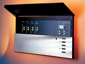
Figure 2. Control panel of the DALI controller.
In the event of a power failure, the DALI controller remembers the current state and when the power is restored, it automatically restores the last operating state. Therefore, the system is not working properly.