Measuring voltage transformers in circuits for relay protection and automation
This article describes how the currents of vast amounts of high-voltage power equipment are modeled with high accuracy for safe use in relay protection circuits— Measuring current transformers in circuits for relay protection and automation.
It also describes how to convert voltages into tens and hundreds of kilovolts to control the operation of relay protection and automation devices based on two principles:
1. transformation of electricity;
2. capacitive separation.
The first method enables a more accurate display of the vectors of the primary quantities and is therefore widespread. The second method is used to monitor a specific phase of the 110 kV network voltage in the bypass buses and in some other cases. But in recent years it has found more and more application.
How Instrument Voltage Transformers Are Made and Operated
The main fundamental difference between measuring voltage transformers (VT) from current transformers (CT) is that they, like all power supply models, are designed for normal operation without short-circuiting the secondary winding.
At the same time, if power transformers are designed to transmit the transported power with minimal losses, then measuring voltage transformers are designed with the aim of high-precision repetition in the scale of the primary voltage vectors.
Principles of operation and devices
The design of a voltage transformer, similar to a current transformer, can be represented by a magnetic circuit with two coils wound around it:
-
primary;
-
second.
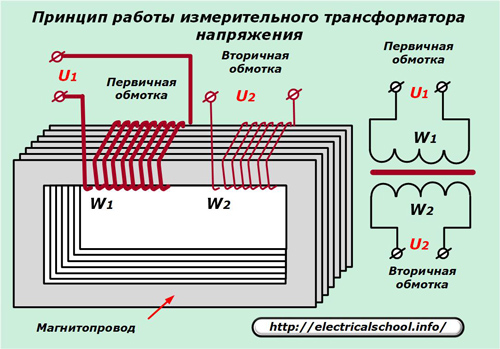
Special grades of steel for the magnetic circuit, as well as the metal of their windings and insulation layer, are selected for the most accurate voltage conversion with the lowest losses. The number of turns of the primary and secondary windings is calculated so that the nominal value of the high-voltage line-to-line voltage applied to the primary winding is always reproduced as a secondary value of 100 volts with the same vector direction for the neutral-grounded systems.
If the primary power transmission circuit is designed with an isolated neutral, then 100 / √3 volts will be present at the output of the measuring coil.
In order to create different methods of simulating primary voltages on the magnetic circuit, not one, but several secondary windings can be located.
VT switching circuits
Instrument transformers are used to measure linear and/or phase primary quantities. To do this, power coils include between:
-
line conductors for controlling line voltages;
-
bus or wire and earth to take the phase value.
An important protective element of measuring voltage transformers is the earthing of their housing and the secondary winding. Caution is given to it because when the primary winding insulation breaks down to the case or to the secondary circuits, the potential for high voltages will appear in them, which can injure people and burn equipment.
Deliberate earthing of the casing and one secondary winding leads this dangerous potential to earth, which prevents further development of the accident.
1. Electrical equipment
An example of connecting a transformer for measuring voltage in a 110 kilovolt network is shown in the photo.
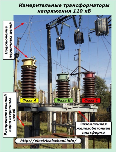
It is emphasized here that the supply wire of each phase is connected by a branch to the terminal of the primary winding of its transformer, located on a common earthed reinforced concrete support, raised at a height safe for electrical personnel.
The body of each measuring VT with the second terminal of the primary winding is grounded directly on this platform.
The outputs of the secondary windings are assembled in a terminal box located at the bottom of each VT. They are connected to the conductors of the cables collected in an electrical distribution box located nearby at a height convenient for servicing from the ground.
It not only switches the circuit, but also installs automatic switches on secondary voltage circuits and switches or blocks to perform operational switching and perform safe maintenance of equipment.
The voltage busbars collected here are fed to the relay protection and automation devices with a special power cable, which is subject to increased requirements to reduce voltage losses. This very important parameter of measurement circuits is discussed in a separate article here — Loss and voltage drop
Cable routes for measuring VT are also protected by metal boxes or reinforced concrete slabs from accidental mechanical damage, just like CT.
Another option for connecting a voltage measuring transformer of the NAMI type, located in a 10 kV grid cell, is shown in the photo below.
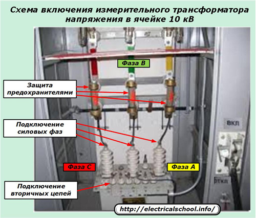 The voltage transformer on the high voltage side is protected by glass fuses in each phase and can be separated from the manual actuator from the supply circuit for performance checks.
Each phase of the primary network is connected to the corresponding input of the supply winding. The conductors of the secondary circuits are brought out with a separate cable to the terminal block.
2. Secondary windings and their circuits
Below is a simple diagram for connecting one transformer to the mains voltage of the supply circuit.
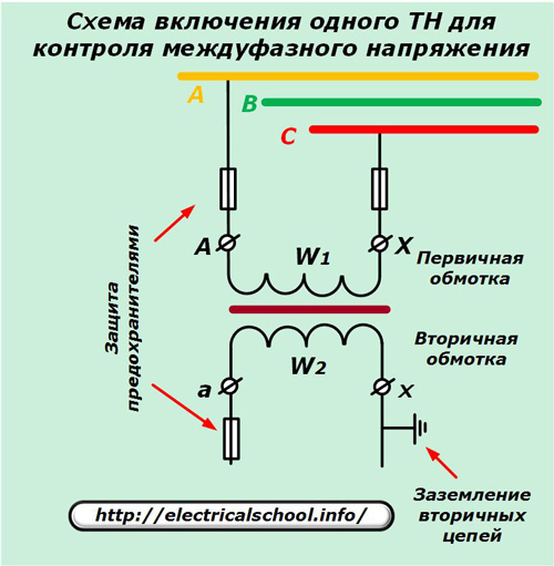
This design can be found in circuits up to and including 10 kV. It is protected on each side by fuses of the appropriate power.
In a 110 kV network, such a voltage transformer can be installed in one phase of the bypass bus system to provide synchronous control of the connected connecting circuits and SNR.

On the secondary side, two windings are used: the main and the additional, which ensure the implementation of the synchronous mode when the circuit breakers are controlled by the block board.
To connect the voltage transformer to two phases of the bypass bus system when controlling the circuit breakers from the main board, the following scheme is used.
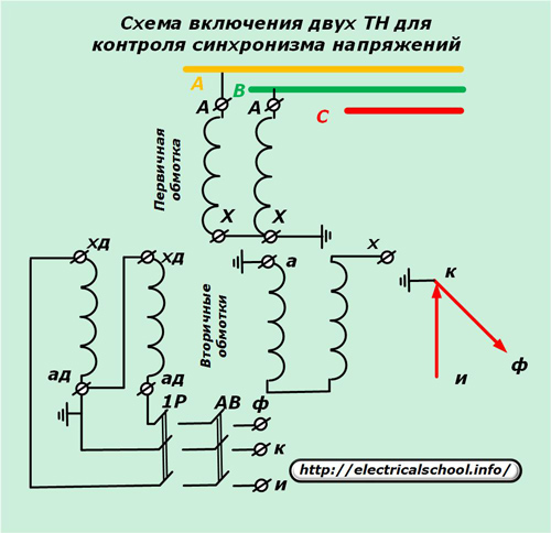
Here, the vector «uk» is added to the secondary vector «kf» formed by the previous scheme.
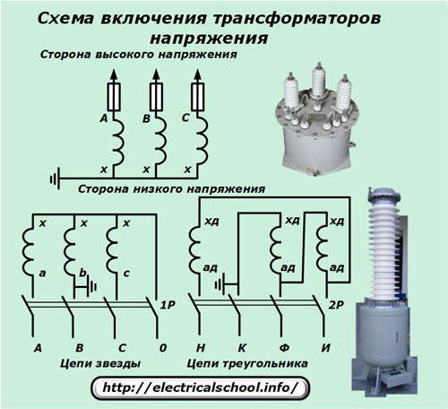
The following scheme is called «open triangle» or incomplete star.

It allows you to simulate a system of two or three phase voltages.
Connecting three voltage transformers according to the full star scheme has the greatest possibilities. In this case, you can get both all phase and line voltages in the secondary circuits.
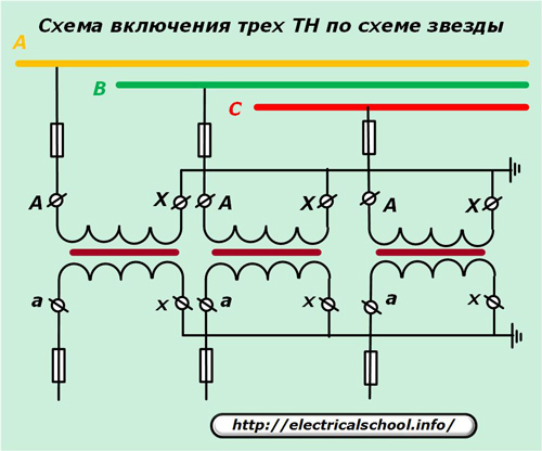
Due to this possibility, this option is used at all critical substations, and the secondary circuits for such VTs are created with two types of windings included according to the star and delta circuit.
The given schemes for turning on the coils are the most typical and far from the only ones. Modern measuring transformers have different capabilities and certain adjustments have been made in the design and connection scheme for them.
Accuracy classes of voltage measuring transformers
To determine errors in metrological measurements, VTs are guided by an equivalent circuit and a vector diagram.

This rather complex technical method makes it possible to determine the errors of each VT measurement in terms of amplitude and angle of deviation of the secondary voltage from the primary and to determine the accuracy class for each tested transformer.
All parameters are measured at nominal loads in the secondary circuits for which the VT is created. If they are exceeded during operation or inspection, then the error will exceed the value of the nominal value.
Measuring voltage transformers have 4 classes of accuracy.
Accuracy classes of voltage measuring transformers
Accuracy classes of VT measurement Maximum limits for permissible errors FU,% δU, min 3 3.0 not defined 1 1.0 40 0.5 0.5 20 0.2 0.2 10
Class No. 3 is used in models operating in relay protection and automation devices that do not require high accuracy, for example, to trigger alarm elements for the occurrence of fault modes in power circuits.
The highest accuracy of 0.2 is achieved by instruments used for critical high-precision measurements when setting up complex devices, conducting acceptance tests, setting up automatic frequency control, and similar work. VTs with accuracy classes 0.5 and 1.0 are most often installed on high-voltage equipment for the transfer of secondary voltage to switchboards, control and regulation meters, relay sets of interlocks, protections and circuit synchronization.
Capacitive voltage draw method
The principle of this method consists in inversely proportional release of voltage on a circuit of capacitor plates of different capacities connected in series.
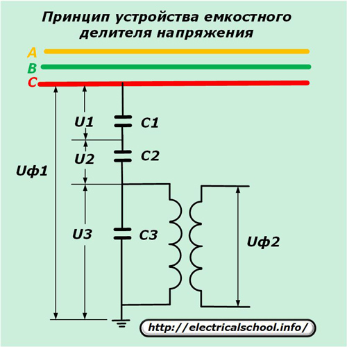
After calculating and selecting the ratings of the capacitors connected in series with the bus or line phase voltage Uph1, it is possible to obtain on the final capacitor C3 the secondary value Uph2, which is removed directly from the container or through a transformer device connected to facilitate settings with adjustable number of coils.
Performance characteristics of measuring voltage transformers and their secondary circuits
Installation requirements
For safety reasons, all VT secondary circuits must be protected. automatic circuit breakers type AP-50 and grounded with a copper wire with a cross-section of at least 4 mm sq.
If a double-bus system is used in the substation, then the circuits of each measuring transformer must be connected through the relay circuit of the repeaters of the disconnector position, which excludes the simultaneous supply of voltage to one relay protective device from different VTs.
All secondary circuits from the terminal node VT to the relay protection and automation devices must be carried out with one power cable so that the sum of the currents of all cores is equal to zero. For this purpose, it is prohibited:
-
separate busbars «B» and «K» and combine them for joint grounding;
-
connect bus “B” to synchronization devices through switch contacts, switches, relays;
-
switch the «B» bus of the counters with the RPR contacts.
Operational switching
All work with operational equipment is carried out by specially trained personnel under the supervision of officials and according to the switching forms. For this purpose, circuit breakers, fuses and automatic switches are installed in the circuits of the voltage transformer.
When a certain section of voltage circuits is taken out of service, the method of verifying the measure taken must be indicated.
Periodic maintenance
During operation, the secondary and primary circuits of the transformers are subjected to various inspection periods, which are tied to the time elapsed since the device was put into operation and include a different scope of electrical measurements and cleaning of the equipment by specially trained repair personnel.
The main malfunction that can occur in voltage circuits during their operation is the occurrence of short-circuit currents between the windings. Most often this happens when electricians do not work carefully in existing voltage circuits.
In the event of an accidental short circuit of the windings, the protective switches located in the terminal box of the measuring VT are turned off, and the voltage circuits supplying the power relays, sets of interlocks, synchronism, distance protections and other devices disappear.
In this case, false activation of existing protections or malfunction of their operation in case of faults in the primary loop is possible. Such short circuits must not only be quickly eliminated, but also include all automatically disabled devices.
Current and voltage measuring transformers are mandatory in every electrical substation. They are necessary for the reliable operation of relay protection and automation devices.