Current transformers — principle of operation and application
 When working with energy systems, it is often necessary to convert certain electrical quantities into analogues similar to them with proportionally changed values. This allows you to simulate certain processes in electrical installations and safely make measurements.
The operation of current transformer (CT) is based on the law of electromagnetic inductionoperating in electric and magnetic fields varying in the form of harmonics of alternating sinusoidal magnitudes.
It converts the primary value of the current vector flowing in the power circuit into a secondary reduced value, respecting modulus proportionality and exact angle transmission.
The principle of operation of the current transformer
The demonstration of the processes taking place during the transformation of electrical energy inside the transformer is explained by the diagram.
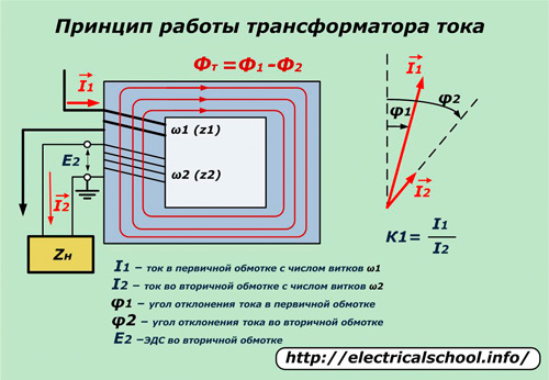
Current I1 flows through the power primary winding with the number of turns w1, overcoming its impedance Z1.A magnetic flux F1 is formed around this coil, which is captured by a magnetic circuit located perpendicular to the direction of the vector I1. This orientation ensures minimal loss of electrical energy when it is converted to magnetic energy.
Crossing the perpendicularly located turns of the winding w2, the flux F1 induces in them an electromotive force E2, under the influence of which a current I2 arises in the secondary winding, overcoming the impedance of the coil Z2 and the connected output load Zn. In this case, a voltage drop U2 is formed at the terminals of the secondary circuit.
The quantity K1 is called, determined by the ratio of the vectors I1 / I2 transformation coefficient... Its value is set during the design of devices and is measured in ready-made structures. The differences between the indicators of real models and the calculated values are evaluated by the metrological characteristic — accuracy class of a current transformer.
In actual operation, the values of the currents in the coils are not constant values. Therefore, the transformation coefficient is usually indicated by nominal values. For example, his expression 1000/5 means that with a primary operating current of 1 kiloampere, 5 ampere loads will act in the secondary turns. These values are used to calculate the long-term performance of this current transformer.
The magnetic flux F2 from the secondary current I2 reduces the value of the flux F1 in the magnetic circuit. In this case, the flux from the transformer Ф created in it is determined by the geometric summation of the vectors Ф1 and Ф2.
Hazardous factors during operation of the current transformer
Ability to be affected by high voltage potential in case of insulation failure
Since the magnetic circuit of the TT is made of metal, has good conductivity and magnetically connects the insulated windings (primary and secondary) to each other, there is an increased risk of electric shock to personnel or equipment damage if the insulation layer is broken.
To prevent such situations, grounding of one of the secondary terminals of the transformer is used to drain the high voltage potential across it in case of accidents.
This terminal is always marked on the housing of the device and is indicated on the connection diagrams.
The possibility of being affected by a high voltage potential in the event of a secondary circuit failure
The conclusions of the secondary winding are marked with «I1» and «I2», so the direction of the currents flowing is polar, coincides in all windings. When the transformer is operating, they must always be connected to the load.
This is explained by the fact that the current passing through the primary winding has a high potential power (S = UI), which is transformed into a secondary circuit with low losses, and when it is interrupted, the current component sharply decreases to the values of leakage through the environment , but at the same time the drop significantly increases the stresses in the broken section.
The potential at the open contacts of the secondary winding during the passage of current in the primary loop can reach several kilovolts, which is very dangerous.
Therefore, all secondary circuits of current transformers must always be securely assembled and shunt short-circuits must always be installed on windings or cores taken out of service.
Design solutions used in current transformer circuits
Each current transformer, as an electrical device, is designed to solve certain problems during the operation of electrical installations. The industry produces a large assortment of them. However, in some cases, when improving structures, it is easier to use ready-made models with proven technologies than to redesign and manufacture new ones.
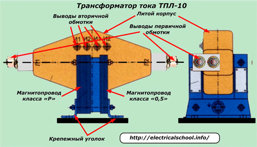
The principle of creating a single-turn TT (in the primary circuit) is basic and is shown in the photo on the left.
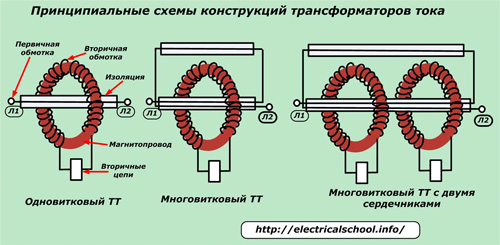
Here the primary winding, covered with insulation, is made of a straight line bus L1-L2 passing through the magnetic circuit of the transformer, and the secondary is wound with turns around it and connected to the load.
The principle of creating a multi-turn CT with two cores is shown on the right. Here two single-turn transformers are taken with their secondary circuits and a certain number of turns of power windings are passed through their magnetic circuits. In this way, not only the power is increased, but the number of output connected circuits is further increased.
These three principles can be changed in different ways. For example, the use of several identical coils around a single magnetic circuit is widespread to create separate, independent secondary circuits that operate autonomously. These are called nuclei. In this way, the protection of switches or lines (transformers) with different purposes is connected to the current circuits of one current transformer.
Combined current transformers with a powerful magnetic circuit, used in equipment emergency modes, and the usual one, designed for measurements at nominal network parameters, work in power equipment devices.Coils wrapped around rebar are used to operate protective devices, while conventional coils are used to measure current or power / resistance.
They are called like this:
-
protective coils marked with index «P» (relay);
-
measurement indicated by the numbers of the metrological accuracy class TT, for example «0.5».
Protective windings during normal operation of the current transformer provide measurement of the primary current vector with an accuracy of 10%. With this value, they are called "ten percent".
Measurement errors
The principle of determining the accuracy of the transformer allows you to evaluate its equivalent circuit shown in the photo. In it, all values of primary quantities are conditionally reduced to action in secondary loops.
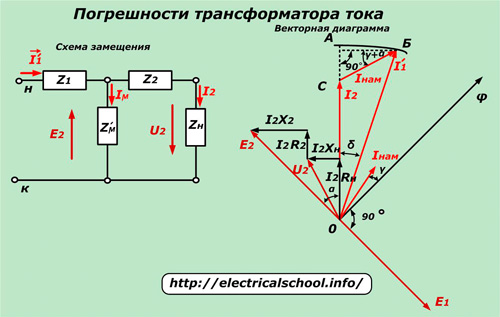
The equivalent circuit describes all the processes operating in the windings, taking into account the energy spent on magnetizing the core with current I.
The vector diagram built on its basis (triangle SB0) shows that the current I2 differs from the values of I'1 with the value of I towards us (magnetization).
The larger these deviations are, the lower the accuracy of the current transformer. To take CT measurement errors into account, the following concepts are introduced:
-
relative current error expressed as a percentage;
-
angular error calculated from the arc length AB in radians.
The absolute value of the deviation of the primary and secondary current vectors is determined by the AC segment.
Common industrial designs of current transformers are manufactured to operate in accuracy classes defined by the characteristics of 0.2; 0.5; 1.0; 3 and 10%.
Practical application of current transformers
A diverse number of their models can be found both in small electronic devices located in a small case and in energy devices that occupy significant dimensions of several meters. They are divided according to operational characteristics.
Classification of current transformers
By agreement, they are divided into:
- measurement, transfer of currents to measuring instruments;
- protected, connected to current protective circuits;
- laboratory, with a high class of accuracy;
- intermediates used for re-conversion.
When operating facilities, TT is used:
-
outdoor outdoor installation;
-
for closed installations;
-
built-in equipment;
-
from above — insert the sleeve;
-
portable, allowing you to take measurements in different places.
By the value of the operating voltage of the TT equipment there are:
-
high voltage (more than 1000 volts);
-
for nominal voltage values up to 1 kilovolt.
Also, current transformers are classified according to the method of insulation materials, the number of transformation steps and other characteristics.
Completed tasks
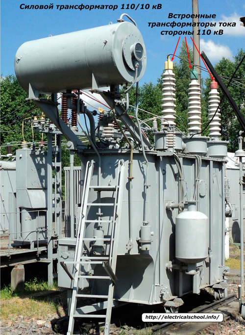
External measuring current transformers are used for the operation of electrical circuits for measuring electrical energy, measurements and protection of lines or power autotransformers.
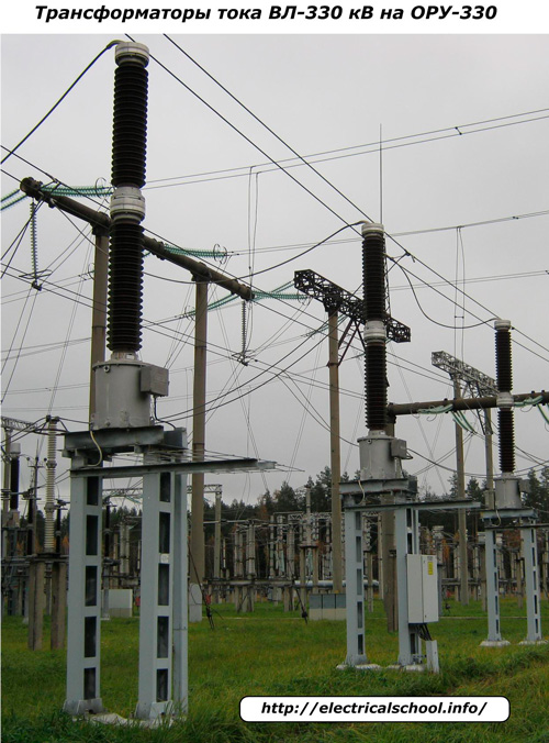
The photo below shows their location for each phase of the line and the installation of secondary circuits in the terminal box of the 110 kV switchgear for the power autotransformer.
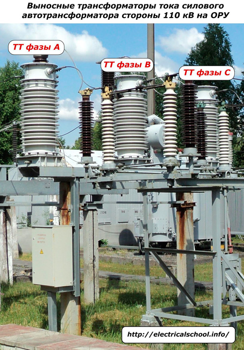
The same tasks are performed by current transformers of the external switchgear-330 kV, but given the complexity of the higher voltage equipment, they have much larger dimensions.
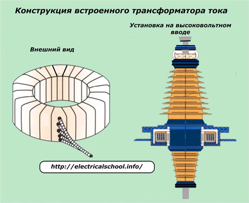
On power equipment, embedded designs of current transformers are often used, which are placed directly on the casing of the power plant.
They have secondary windings with leads placed around the high voltage bushing in a sealed housing. The cables from the CT clamps are routed to the terminal boxes attached here.
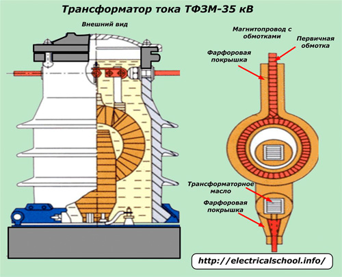
Internal high-voltage current transformers most often use special transformer oil as an insulator. An example of such a design is shown in the photo for current transformers of the TFZM series designed to operate at 35 kV.
Up to and including 10 kV, solid dielectric materials are used for insulation between the windings in the manufacture of the box.
An example of a current transformer TPL-10 used in KRUN, closed switchgear and other types of switchgear.
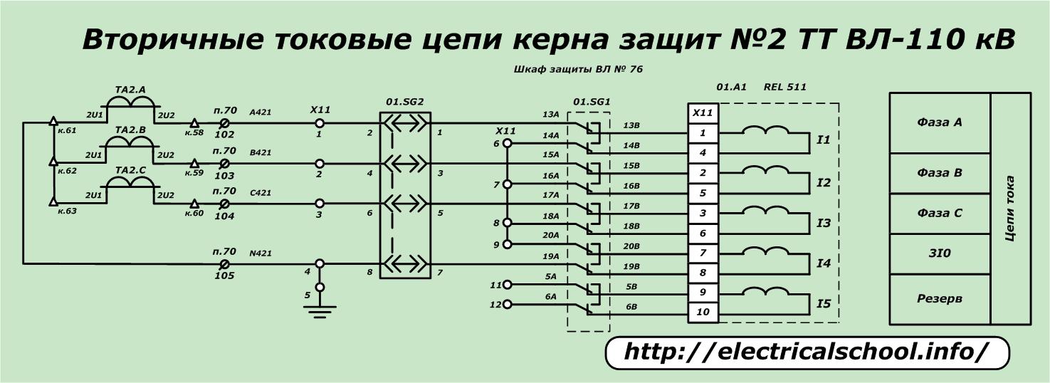
An example of connecting the secondary current circuit of one of the REL 511 protection cores for a 110 kV circuit breaker is shown with a simplified diagram.
Current transformer faults and how to find them
A current transformer connected to a load can break the electrical resistance of the insulation of the windings or their conductivity under the influence of thermal overheating, accidental mechanical influences or due to poor installation.
In operational equipment, the insulation is most often damaged, resulting in turn-to-turn short-circuiting of the windings (reduction in transmitted power) or the occurrence of leakage currents through randomly created short-circuit circuits.
In order to identify the places of poor-quality installation of the power circuit, inspections of the working circuit with thermal imagers are periodically carried out.Based on them, the defects of broken contacts are immediately removed, overheating of the equipment is reduced.
The absence of closing from turn to turn is checked by the specialists of the relay protection and automation laboratories:
-
taking the current-voltage characteristic;
-
charging the transformer from an external source;
-
measurements of the main parameters in the working scheme.
They also analyze the value of the transformation coefficient.
In all works, the ratio between the primary and secondary current vectors is estimated by magnitude. Their angle deviations are not performed due to the lack of high-precision phase measuring devices that are used to check current transformers in metrological laboratories.
High-voltage tests of dielectric properties are assigned to the specialists of the insulation service laboratory.