Drive power factor
 Drive power factor — the ratio of active power consumed by the electric drive to apparent power. For sinusoidal voltage and current, the power factor is equal to the cosine of the phase angle between the voltage and current curves (cosφ).
At a constant active power consumed by the electric drive, the increase in reactive power and, accordingly, the decrease in the power factor causes an increase in the total current in the wires of the connections of the electrical system (generators, transmission lines, etc.). This leads to an increase in the cost of ferrous and non-ferrous metals, insulating materials, dimensions, weighing of auxiliary equipment, etc.
In addition, an increase in reactive power increases voltage losses and thus sharply worsens the conditions for voltage regulation and prevents the normal operation of parallel-connected generators. All this determines the desire to have high cosφ electrical installations.
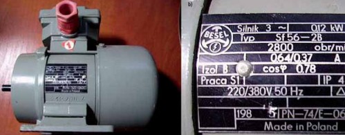
In industrial enterprises, the main consumers of reactive power are three-phase asynchronous motors, which represent more than 70% of the total reactive power, and transformers — up to 20%.
A noticeable reduction in reactive loads is achieved by correctly choosing the rated power of asynchronous motors for driving running machines, switching underloaded asynchronous motors from delta to star or replacing them with less powerful ones, using idle limiters in the control circuits of asynchronous motors, improving the quality of their repair, as well as using synchronous motors instead of asynchronous ones (where possible according to the conditions of the technological process).
Read more about it here: How to improve power factor without compensating capacitors
Further reduction of reactive loads is possible with the help of compensating devices (capacitors and overexcited synchronous machines) installed on the user or in close proximity to him.
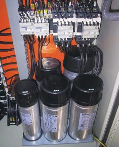
The amount of reactive power generated by capacitors is directly proportional to their capacitance and the square of the line voltage into which these capacitors are connected.
When a synchronous machine is used as a compensator, a reduction in reactive power is achieved due to additional energy losses—no-load losses of the machine and power that will excite it.
To maintain cosφ at the required level, with fluctuations in the reactive load, it is necessary to use automatic control of the excitation of a synchronous machine or an automatic change in the number of included capacitors.
The required power of the compensating device is given by the expression
Bc = (Wа (tgφ1 — tgφ2) α)/ Tp, kvar
where Wа — active energy consumption for the busiest month (kWh), tgφ1— the tangent of the phase angle corresponding to the weighted average cosine for the busiest month, tgφ2— the tangent of the phase angle, the cosine of which must be taken within 0 .92 — 0.95, α — a calculated coefficient equal to 0.8-0.9, taking into account the possibility of increasing cosφ on an existing plant by improving the operating modes of electrical equipment (for newly designed plants, this coefficient is taken equal to per one), TNS — the number of hours of operation of the enterprise during the month.