Solenoid control relays, how the relay works
A relay is an electrical device designed to switch electrical circuits (abruptly change output values) for given changes in electrical or non-electrical input values.
Relay elements (relays) are widely used in control and automation circuits because they can be used to control large output powers with low power input signals; fulfill logical operations; creation of multifunctional relay devices; to carry out switching of electrical circuits; to fix deviations of the controlled parameter from the set level; performs the functions of a memory element, etc.
The first relay was invented by the American J. Henry in 1831 and based on the electromagnetic principle of operation, it should be noted that the first relay was not a switching relay, but the first switching relay was invented by the American S.Breeze Morse in 1837, who later used in a telegraph apparatus ... The word relay comes from the English relay, which means changing tired post horses at stations or passing the baton (baton) to a tired athlete.
Relay classification
Relays are classified according to different criteria: according to the type of input physical quantities to which they react; by the functions they perform in management systems; by design, etc. According to the type of physical quantities, electrical, mechanical, thermal, optical, magnetic, acoustic, etc. are distinguished. relay. It should be noted that the relay can respond not only to the value of a certain quantity, but also to the difference in values (differential relays), to a change in the sign of a quantity (polarized relays), or to the rate of change of an input quantity.
Relay device
A relay usually consists of three main functional elements: sense, intermediate and executive.
A perceiving (primary) element perceives the controlled quantity and transforms it into another physical quantity.
An intermediate element compares the value of this value with the setpoint and when it is exceeded, transmits the first action to the drive.
An actuator transfers the effect from the relay to the controlled circuits. All these elements can be expressed or combined with each other.
The sensitive element, depending on the purpose of the relay and the type of physical quantity to which it responds, can have a different design, both in terms of the principle of operation and in terms of the device.For example, in an overcurrent relay or a voltage relay, the sensitive element is made in the form of an electromagnet, in a pressure switch - in the form of a membrane or sleeve, in a level switch - in a float, etc.
By the device of the drive, the relays are divided into contact and non-contact.
Contact relays act on the controlled circuit by means of electrical contacts, the closed or open state of which makes it possible to provide either a complete short circuit or a complete mechanical interruption of the output circuit.
Contactless relays affect the controlled circuit through a sudden (abrupt) change in the parameters of the output electrical circuits (resistance, inductance, capacitance) or a change in the voltage level (current).
Relay characteristics
 The main characteristics of the relay are determined by the dependencies between the parameters of the output and input quantities.
The following main characteristics of the relay are distinguished.
1. The relay actuation magnitude Xcr — the input value parameter value at which the relay is turned on. When X < Xav, the output value is equal to Umin, when X ³ Xav, the value of Y abruptly changes from Umin to Umax and the relay turns on. The acceptance value by which the relay is adjusted is called the setpoint.
2. Relay actuation power Psr — the minimum power that must be provided to the receiving organ to transfer it from a state of rest to a state of operation.
3. Controlled power Rupr — the power that is controlled by the switching elements of the relay in the switching process.Regarding the control power, a distinction is made between relays for low-power circuits (up to 25 W), relays for medium-power circuits (up to 100 W) and relays for high-power circuits (over 100 W), which belong to the power relays and are called contactors.
4. Relay response time tav — the time interval from the Xav signal to the relay input to the start of the action on the controlled circuit. According to the response time, there are normal, high-speed, delayed relays and time relays. Usually for normal relays tav = 50 ... 150 ms, for high-speed relays tav 1 s.
The principle of operation and the device of electromagnetic relays
Due to its simple principle of operation and high reliability, electromagnetic relays are widely used in automation systems and in electrical installation protection schemes. Electromagnetic relays are divided into DC and AC relays. DC relays are divided into neutral and polarized. Neutral relays respond equally to direct current in both directions flowing through its coil, and polarized relays respond to the polarity of the control signal.
The operation of electromagnetic relays is based on the use of electromagnetic forces that arise in a metal core when current passes through the turns of its coil. The relay parts are mounted on the base and covered with a cover. A movable armature (plate) with one or more contacts is mounted above the core of the electromagnet. Opposite them are the corresponding paired fixed contacts.
In the initial position, the anchor is held by a spring. When voltage is applied, the electromagnet attracts the armature, overcoming its force and closes or opens the contacts, depending on the design of the relay.After de-energizing, the spring returns the armature to its original position. Some models may have built-in electronic components. This is a resistor connected to the coil winding for clearer relay actuation, or / and a capacitor parallel to the contacts to reduce arcing and noise.
The controlled circuit is not electrically connected in any way to the control circuit; moreover, in the controlled circuit the value of the current can be much higher than in the control circuit. That is, relays essentially act as an amplifier for current, voltage, and power in an electrical circuit.
AC relays operate when a current of a certain frequency is applied to their coils, that is, the main source of energy is the AC network. The construction of the AC relay is similar to that of the DC relay, only the core and armature are made of electrical steel sheets to reduce hysteresis losses and eddy currents.
Advantages and disadvantages of electromagnetic relays
 The electromagnetic relay has a number of advantages that semiconductor competitors do not have:
- ability to switch loads up to 4 kW with relay volume less than 10 cm3;
- resistance to impulse surges and destructive disturbances resulting from lightning discharges and as a result of switching processes in high voltage electrical engineering;
- exceptional electrical isolation between the control circuit (coil) and the contact group — the latest 5 kV standard is an unattainable dream for the majority of semiconductor switches;
- low voltage drop across closed contacts and, as a result, low heat generation: when switching a current of 10 A, a small relay dissipates a total of less than 0.5 W across the coil and contacts, while a triac relay emits more than 15 W to the atmosphere, which, firstly, requires intensive cooling, and secondly, worsens the greenhouse effect on the planet;
- extremely low cost of electromagnetic relays compared to solid state switches
Noting the advantages of electromechanics, we also note the disadvantages of the relay: low speed of operation, limited (although very large) electrical and mechanical resource, creation of radio interference when closing and opening contacts, and finally, the last and unpleasant property — problems with switching inductive loads and high voltage DC loads.
A typical application practice of high-power electromagnetic relays is the switching of loads at 220 V AC or 5 to 24 V DC at switching currents up to 10-16 A. servo), incandescent lamps, electromagnets and other active, inductive and capacitive consumers of electrical energy in the range from 1 W to 2-3 kW.
Polarized electromagnetic relays
One type of electromagnetic relay is a polarized electromagnetic relay. Their main difference from neutral relays is the ability to respond to the polarity of the control signal.
The most common series of electromagnetic control relays
 Intermediate relay RPL series. The relays are intended for use as components in stationary installations, mainly in control circuits for electric drives at voltages up to 440 V DC and up to 660 V AC with a frequency of 50 and 60 Hz.The relays are suitable for operation in control systems using microprocessor technology where the closing coil is surrounded by a limiter limiter or with thyristor control. If necessary, one of the following can be installed on the intermediate relay. plugins PKL and PVL… Nominal current of the contacts — 16A
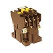
Intermediate relay series RPU-2M. Intermediate relays RPU-2M are designed for operation in electrical circuits for control and industrial automation of alternating current with voltage up to 415V, frequency 50Hz and direct current with voltage up to 220V.
Relay series RPU-0, RPU-2, RPU-4. Relays are produced with DC pickup coils for voltages 12, 24, 48, 60, 110, 220 V and currents of 0.4 — 10 A and AC pickup coils for voltages 12, 24, 36, 110, 127, 220, 230, 240, 380 and currents 1 — 10 A. Relay RPU-3 with supply coils DC — for voltages 24, 48, 60, 110 and 220 V.
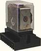
 Intermediate relay series RP-21 are intended for use in control circuits of alternating current electric drives with a voltage of up to 380V and in DC circuits with a voltage of up to 220V. RP-21 relays are equipped with sockets for soldering, for din. rail or screw.
The main characteristics of the RP-21 relay. Supply voltage range, V: DC — 6, 12, 24, 27, 48, 60, 110 AC with a frequency of 50 Hz — 12, 24, 36, 40, 110, 127, 220, 230, 240 AC with a frequency of 60 Hz — 12, 24, 36, 48, 110, 220, 230, 240 Rated contact circuit voltage, V: DC relay — 12 … 220, AC relay — 12 … 380 Rated current — 6.0 A Quantity contacts closed . / rest / switch — 0 … 4/0 … 2/0 … 4 Mechanical durability — at least 20 million cycles.
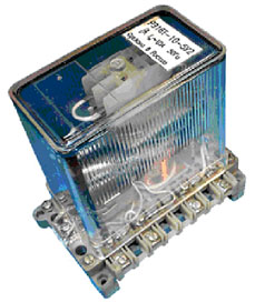
Electromagnetic DC relay RES-6 series as intermediate relay with voltage 80 — 300 V, switching current 0.1 — 3 A
It is also used as an intermediate series of electromagnetic relaysRP-250, RP-321, RP-341, RP-42 and a number of others that can be used as a voltage relay.
How to choose an electromagnetic relay
 The operating voltages and currents in the relay coil must be within the permissible values. A decrease in the operating current in the coil leads to a decrease in the reliability of the contact and an increase in the overheating of the coil, a decrease in the reliability of the relay at the maximum permissible positive temperature. Even a short-term supply with an increased operating voltage to the relay coil is undesirable, since this causes mechanical overvoltages in parts of the magnetic circuit and contact groups, and the electrical overvoltage of the coil when the circuit is opened can cause insulation breakdown.
When choosing the mode of operation of relay contacts, it is necessary to take into account the value and type of switched current, the nature of the load, the total number and frequency of switching.
When switching active and inductive loads, the most difficult for the contacts is the process of opening the circuit, because in this case, due to the formation of an arc discharge, the main wear of the contacts occurs.
How to rewind the windings of the coils of electrical devices to a different type of current