Circuit breakers
How the circuit breaker works
Automatic switches (switches, breakers) are electrical switching devices designed to conduct circuit current in normal modes and to automatically protect electrical networks and equipment from emergency modes (short-circuit currents, overload currents, reduction or disappearance of voltage, change in direction) of the current, the appearance of magnetic fields of powerful generators in emergency conditions, etc.), as well as for infrequent commutation of the rated currents (6-30 times a day).
Due to their simplicity, convenience, maintenance safety and reliability of protection against short circuit currents, these devices are widely used in low and high power electrical installations.
Circuit breakers are manual switching devices, but many types have an electromagnetic or electric motor drive, making it possible to operate them remotely.
 Operating principle
The machines are usually turned off manually (by drive or remote control), and in case of a violation of normal operation (occurrence of overcurrent or voltage reduction) — automatically.In this case, each machine is supplied with an overvoltage release, and in some types with an undervoltage release.
According to the protective functions performed, circuit breakers are divided into automatic machines: overcurrent, undervoltage and reverse power.
Circuit breakers are used to automatically open an electrical circuit when short-circuit and overload currents occur in it above the set limit. By replacing the switch and fuse, they provide more reliable and selective protection under abnormal conditions.
If the environmental conditions differ from normal (humidity of the air is higher than 85% and contains impurities of harmful vapors), then the circuit breakers should be placed in boxes and cabinets of dust-moist and chemically resistant construction.
Classification
Circuit breakers are subdivided into:
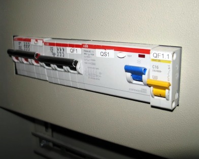
- installation circuit breakers have a protective insulating (plastic) casing and can be installed in public places;
- universal - they do not have such a case and are intended for installation in distribution devices;
- acting quickly (its own reaction time does not exceed 5 ms);
- slow (from 10 to 100 ms);
The speed is provided by the very principle of operation (polarized electromagnetic or induction-dynamic principles, etc.), as well as by the conditions for rapid extinguishing of the electric arc. A similar principle is used in current limiting machines;
- selective adjustable response time in the area of short-circuit currents;
- circuit breakers with reverse current that are activated only when the direction of the current in the protected circuit changes;
- Polarized automatic machines turn off the circuit only when the current rises in the forward direction, non-polarized - with any direction of current.
 Design
The design characteristics and the principle of operation of the machine are determined by its purpose and scope.
Switching the machine on and off can be done manually, with an electric motor or an electromagnetic drive.
The manual drive is used for rated currents up to 1000 A and provides a guaranteed final switching capacity, regardless of the speed of movement of the closing handle (the operator must carry out the switching operation decisively: start - bring it to the end).
Electromagnetic and electric motor drives are powered by voltage sources. The control circuit of the drive must have protection against repeated short-circuiting, while the process of turning on the machine to the limiting short-circuit currents must stop at a supply voltage of 85-110% of the nominal.
In the event of overload and short circuit currents, the circuit breaker will trip regardless of whether the control handle is held in the closed position.
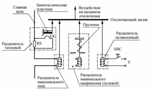
An important part of the machine is a release, which controls the set parameter of the protected circuit and acts on the tripping device, which trips the circuit breaker. In addition, the release allows remote shutdown of the machine. The most common editions are the following types:
- electromagnetic for protection against short-circuit currents;
- thermal for overload protection;
- combined;
- semiconductor with high stability of response parameters and easy tuning.
Circuit breakers without releases can be used for switching a circuit without current or for infrequent switching of rated current.
The series of circuit breakers produced by the industry are designed to be used in different climatic zones, placed in places with different working conditions, to work in conditions that are different in terms of mechanical stress and explosiveness of the environment, and have different degree of protection against touch and external influences.
Information on specific types of devices, their standard versions and standard sizes is given in the normative and technical documents. As a rule, such a document is the Technical Conditions (TU) of the plant... In some cases, in order to unify products that are widely used and produced by several enterprises, the level of the document is raised (sometimes to the level of the State Standard).
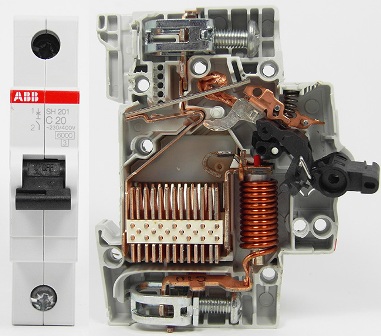
Circuit breakers consist of the following main components:
- contact system;
- arc extinguishing system;
- liberating;
- control mechanism;
- free release mechanism.
A contact system consists of fixed contacts fixed in the housing and movable contacts mounted hinged on the semi-axis of the lever of the control mechanism and usually provides a single circuit break.
An arc extinguishing device is installed in each pole of the circuit breaker and is designed to localize an electric arc in a limited volume. It is an arc chamber with a grid of deionized steel plate. Spark arrestors in the form of fiber plates can also be provided.
A free release mechanism is a hinged 3- or 4-link mechanism that provides release and deactivation of the contact system in both automatic and manual operation.
An electromagnetic overcurrent release, which is an armature electromagnet, provides automatic tripping of the circuit breaker at short circuit currents exceeding the current setting. Electromagnetic current releases with hydraulic delay device have an inverse time delay to protect against overload currents.
Thermal overload relief is a thermobimetallic plate. At overload currents, the deformation and forces of this plate ensure automatic tripping of the circuit breaker. The delay decreases as the current increases.
Semiconductor tripping units consist of a measuring element, a block of semiconductor relays and an output electromagnet acting on the free release mechanism of the machine. A current transformer (AC) or an amplifier with a magnetic choke (DC) is used as the measuring element.
The semiconductor current release allows the following parameters to be adjusted:
- rated discharge current;
- setting for operating current in the area of short-circuit currents (interrupting current);
- response time settings in the congestion zone;
- response time settings in the area of short-circuit currents (for selective switches).
Many circuit breakers use combination releases that use thermal elements to protect against overload currents and electromagnetic elements to protect against short-circuit currents without time delay (interruption).
The circuit breaker also has additional assemblies that are built into the circuit breaker or attached to it externally.They can be independent, zero and low voltage, free and auxiliary contacts, manual and electromagnetic remote drive, automatic shutdown signaling, device for locking the circuit breaker in the "off" position.
The shunt trip is an electromagnet powered by an external voltage source. Sub and zero releases can be time-delayed and non-time-delayed. With the help of a shunt or undervoltage release, remote shutdown of the machine is possible.
Operating conditions
The switches are available in versions with different degrees of protection against touch and external influences (IPOO, IP20, IP30, IP54). In this case, the degree of protection of the terminals for connecting external wires may be lower than the degree of protection of the switch housing.
The switches are produced in 5 climate versions and 5 placement categories, which are coded with letters U, UHL, T, M, OM and numbers 1,2,3,4,5.
The switches are designed for continuous operation under the following conditions:
- installation at an altitude of no more than 1000 m (switches of the AP50 and AE1000 series — at an altitude of no more than 2000 m above sea level);
- ambient air temperature from — 40 (without dew and frost) to + 40 ° C (for AE1000 series switches — from +5 to + 40 ° C);
- relative humidity of the environment not more than 90% at 20 ° C and not more than 50% at 40 ° C;
- environment - non-explosive, not containing dust (including conductive) in an amount that disrupts the operation of the circuit breaker, and corrosive gases and vapors in concentrations that destroy metals and insulation;
- place of installation of the switch — protected from water, oil, emulsion, etc.;
- lack of direct exposure to solar and radioactive radiation;
- lack of sharp shocks (blows) and strong shaking; vibration of the mounting points of the switches with a frequency of up to 100 Hz with an acceleration of no more than 0.7 g is allowed.
The groups of operating conditions for electrical products with regard to the impact of the mechanical factors of the external environment are determined by GOST 17516.1-90. According to the catalog data, the circuit breakers are designed for operation in groups Ml, M2, MZ, M4, Mb, M9, M19, M25.
In terms of safety, circuit breakers comply with GOST 12.2.007.0-75 and GOST 12.2.007.6-75, the requirements of the «Rules for electrical installations» and ensure the operating conditions determined by the «Rules for the technical operation of installations» by the User «and» Safety rules for the operation of electrical installations by the user «, approved by the State Energy Supervision Service on 12.21.94. With regard to protection against leakage currents, circuit breakers meet the requirements of GOST 12.1. 038-82.
Non-working work (storage and transportation during work breaks) is in accordance with GOST 15543-70 and GOST 15150-69.
Also read on this topic: Circuit breaker, circuit breaker, RCD — what's the difference?