Electric circuits with direct current
In a single circuit An electric circuit with a direct current EMF directed inside the source of electrical energy from the negative pole to the positive excites a current I the same direction, which is determined by Ohm's Law for the entire circuit:
I = E / (R + RTuesday),
where R is the resistance of the external circuit consisting of the receiver and connecting wires, RW is the resistance of the internal circuit that includes the source of electrical energy.
If the resistances of all elements of the electric circuit do not depend on the value and direction of the current and EMF, then they, as well as the circuit itself, are called linear.
In a single-loop linear DC electrical circuit with a single source of electrical energy, the current is directly proportional to the EMF and inversely proportional to the total resistance of the circuit.
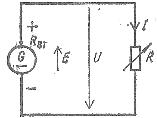
Rice. 1. Diagram of a single-circuit electric circuit with direct current
From the above formula it follows that E — RwI = RI, where I = (E — PvI) / R or I = U / R, where U = E — RwI is the voltage of the source of electrical energy, which is directed from the positive pole to the negative pole.

Expression I = U / R is Ohm's law for a section of a circuit, to the terminals to which a voltage U is applied, coinciding in direction with the current I at the same site.
Voltage versus current U(I) at E = const and RW = const is called the external or volt-ampere characteristic of a linear source of electrical energy (Fig. 2), according to which it is possible for any current I to determine the corresponding voltage U and according to the formulas , given below — calculate the power of the receiver of electrical energy:
P2 = RI2 = E2R / (R + RTuesday)2,
source of electrical energy:
P1 = (R + RTuesday) Az2 = E2 / (R + RTuesday)
and the efficiency of the installation in DC circuits:
η = P2 / P1 = R / (R + Rwt) = 1 / (1 + RWt / R)
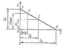
Rice. 2. External (volt-ampere) characteristic of the source of electrical energy
Point X of the current-voltage characteristic of the source of electrical energy corresponds to the idle mode (x.x.) In an open circuit, when the current Azx = 0 and the voltage Ux = E.
Point H determines the nominal mode if the voltage and current correspond to their nominal values Unom and Aznom, given in the passport of the source of electrical energy.
Point K characterizes the short-circuit mode (short circuit), which occurs when the terminals of the source of electrical energy are connected to each other, in which the external resistance R =0. In this case, a short-circuit current Azk = E / Rwatt occurs, which is times higher than the nominal current Aznom due to the fact that internal resistance of the source electrical energy Rw <R.In this mode, the voltage at the terminals of the source of electrical energy Uk = 0.
Point C corresponds to the matched mode where the resistance of the external circuit R is equal to the resistance of the internal target Rwatt source of electrical energy. In this mode, there is a current Ic = E / 2R, the power of the external circuit corresponds to the highest power P2max = E2 / 4RW and the efficiency (efficiency) of the installation ηc = 0.5.
Contract regime where:
P2 / P2max = 4R2 / (R + Rtu)2 = 1 and Ic = E / 2R = I
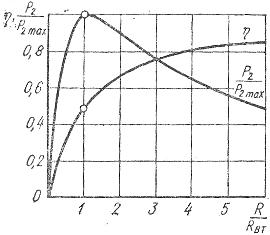
Rice. 3. Graphs of the dependences of the relative power of the receiver of electrical energy and the efficiency of the installation on the relative resistance of the receiver
In power plants, the modes of electric circuits differ significantly from the coordinated mode and are characterized by currents I << Ic due to the resistances of the receivers R Rvat, as a result of which the operation of such systems proceeds with high efficiency.
The study of phenomena in electric circuits is simplified by replacing them with equivalent circuits — mathematical models with ideal elements, each of which is characterized by one and the parameters taken from the parameters of the swept elements. These diagrams fully reflect the properties of electrical circuits and, if certain conditions are met, facilitate an analysis of the electrical condition of electrical circuits.
In equivalent circuits with active elements, an ideal EMF source and an ideal current source are used.
An ideal EMF source characterized by a constant EMF, E, and an internal resistance equal to zero, as a result of which the current of such a source is determined by the resistance of the connected receivers, and a short circuit causes current and power theoretically tending to an infinitely large value.
An ideal power source is assigned an internal resistance tending to an infinitely large value and a constant current Azdo regardless of the voltage at its terminals, equal to the short-circuit current, as a result of which an unlimited increase in the load connected to the source is accompanied by theoretically unlimited increase in voltage and power.
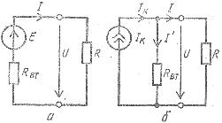
Rice. 4. Backup circuits for an electric circuit with a real source of electrical energy and a resistor, a - with an ideal source of EMF, b - with an ideal source of current.
Real sources of electrical energy with EMF E, internal resistance Rvn and short-circuit current Ic can be represented by equivalent circuits that include an ideal emf source or an ideal current source, respectively, with resistive elements connected in series and in parallel, which characterize the internal parameters of a real source and limiting the power of the connected receivers (Fig. 4, a, b).
Real sources of electrical energy operate in regimes close to the regime of ideal EMF sources, if the resistance of the receivers is large compared to the internal resistance of real sources, i.e. when they are in regimes close to the idle mode.
In cases where the operating modes are close to the mode short circuit, real sources approach ideal current sources because the resistance of the receivers is small compared to the internal resistance of real sources.