Electromagnetic contactors
Contactors are remote-operated devices designed for frequent switching on and off of electrical circuits during normal operation.
An electromagnetic contactor is an electrical device designed for switching power supply circuits. The closing or opening of the contacts of the contactor is most often carried out using an electromagnetic drive.
Classification of electromagnetic contactors
Common industrial contactors are classified as:
- by the nature of the current of the main circuit and the control circuit (including windings) — direct, alternating, direct and alternating current;
- by the number of main poles — from 1 to 5;
- for the nominal current of the main circuit — from 1.5 to 4800 A;
- by nominal voltage of the main circuit: from 27 to 2000 V DC; from 110 to 1600 VAC with a frequency of 50, 60, 500, 1000, 2400, 8000, 10,000 Hz;
- at rated voltage closing coil: from 12 to 440 V DC, from 12 to 660 V AC with a frequency of 50 Hz, from 24 to 660 V AC with a frequency of 60 Hz;
- according to the presence of auxiliary contacts - with contacts, without contacts.
Contactors also differ in the type of connection of the wires of the main circuit and the control circuit, the method of installation, the type of connection of external wires, etc.
These characteristics are reflected in the type of contactor specified by the manufacturer.
Normal operation of the contactors is allowed
- when the voltage at the terminals of the main circuit is up to 1.1 and the control circuit is from 0.85 to 1.1 of the rated voltage of the corresponding circuits;
- when the AC voltage drops to 0.7 of rated, the closing coil should hold the armature of the contactor solenoid in the fully pulled position and not hold it when the voltage is removed.
 The series of electromagnetic contactors produced by the industry are designed for use in different climatic zones, work under different conditions determined by the location during operation, mechanical loads and explosion hazard of the environment and, as a rule, do not have special protection against contact and external influences.
Design of electromagnetic contactors
The contactor consists of the following main components: main contacts, arc system, electromagnetic system, auxiliary contacts.
The main contacts close and open the power circuit. They must be designed to carry the rated current for a long time and to produce a large number of turns on and off at their high frequency. The position of the contacts is considered normal when the contactor retractor coil is not current and all available mechanical locks are released. The main contacts can be of lever and bridge type. The lever contacts adopt a rotating movable system, the bridge contacts - rectilinear.
Arc chambers for direct current contactors are built on the principle of extinguishing an electric arc by means of a transverse magnetic field in chambers with longitudinal slots. Magnetic field in most designs, it is excited by an arc extinguishing coil connected in series with the contacts.
An arc extinguishing system provides extinguishing of the electric arc that occurs when the main contacts are opened. Arc extinguishing methods and the design of arc extinguishing systems are determined by the type of current in the main circuit and the way the contactor operates.
A contactor electromagnetic system provides remote control of the contactor, i.e. on and off. The design of the system is determined by the type of current and control circuit of the contactor and its kinematic diagram. The electromagnetic system consists of a core, armature, coils and fasteners.
The contactor's electromagnetic system can be designed to close the armature and hold it closed, or only to close the armature. Keeping it in the closed position in this case is done by a lock.
The contactor is turned off after the coil is turned off under the action of the opening spring or the own weight of the moving system, but more often the spring.
Auxiliary contacts. They switch in the control circuits of the contactor, as well as in the blocking and signaling circuits. They are designed for continuous conduction of current not more than 20 A and disconnection current not more than 5 A. Contacts are made both when closing and when opening, in most cases of the bridge type.
AC contactors are available with deionic circuit breakers.When the arc occurs, it moves to the grid, breaks up into a series of small arcs, and is extinguished at the moment the current crosses zero.
Schemes for connecting a contactor consisting of functional conductive elements (control coils, main and auxiliary contacts) in most cases have a standard form and differ only in the number and type of contacts and coils.
Important contactor parameters are rated operating currents and voltages.
 Contactor rated current — this is the current that is determined by the heating conditions of the main circuit in the absence of switching on or off the contactor. In addition, the contactor is able to withstand this current of three closed main contacts for 8 hours, and the temperature rise of its various parts must not be more than the permissible value. In the case of intermittent operation of the apparatus, the concept of the permissible equivalent current of continuous operation is often used.
Contactor Main Circuit Voltage — The highest rated voltage for which the contactor is designed to operate. If the rated current and voltage of the contactor determine the maximum permissible operating conditions for it in continuous operation, then the rated operating current and operating voltage are determined by these operating conditions. Thus, the nominal operating current, which determines the use of the contactor under the given conditions established by the manufacturer, depending on the nominal operating voltage, the nominal operating mode, the category of use, the type of construction and the operating conditions. And nominal operating voltage is equal to the mains voltage at which the contactor can operate under the given conditions.
Contactors must be selected in accordance with the following basic technical parameters:
1) by purpose and scope;
2) by category of use;
3) in terms of mechanical and switching wear resistance;
4) according to the number and design of the main and auxiliary contacts;
5) by the character of the current and the values of the nominal voltage and current of the main circuit;
6) according to the rated voltage and power consumption of the switching coils;
7) according to the mode of operation;
8) by climate design and placement category.
DC contactors are designed to switch DC circuits and are typically driven by a DC electromagnet. AC contactors are designed to switch AC circuits. The electromagnets of these circuits can be AC or DC.
DC contactors.
 Currently, the use of DC contactors and their new development are reduced accordingly. DC contactors are produced mainly for voltages 22 and 440 V., currents up to 630 A., single-pole and double-pole.
Contactors of the KPD 100E series are designed for switching main circuits and control circuits of a direct current electric drive with a voltage of up to 220V.
Contactors are available for rated currents from 25 to 250 A.
Contactors of the KPV 600 series are designed for switching the main circuits of electric drives with direct current. The contactors of this series are available in two versions: with one normally open contact (KPV 600) and with one normally open contact (KPV 620).
The contactors are controlled by the DC network.
Contactors are produced for nominal currents from 100 to 630 A. A contactor for a current of 100 A has a mass of 5.5 kg, for 630 A — 30 kg.
AC contactors: KT6000, KT7000
CT (KTP) — X1 X2 X3 X4 S X5
X1 — serial number, 60, 70.
X2 — contactor size: 0, 1, 2, 3, 4, 5, 6.
X3 — number of poles: 2, 3, 4, 5.
X4 — additional meaning of the specific characteristics of the series:B — modernized contacts; A — increased switching capacity at voltage 660V.
C — silver-based metal-ceramic contacts. The absence of a letter means that the contacts are copper.
X5 — Climatic characteristics: U3, UHL, T3.
AC contactors are generally built three-pole with closing main contacts. Electromagnetic systems are made lined, that is, assembled from separate insulated plates with a thickness of up to 1 mm. Low impedance coils with a small number of turns. The main part of the resistance of the coil is its inductive resistance, which depends on the size of the gap. Therefore, the current in the AC contactor coil with an open system is 5-10 times higher than the current with a closed magnetic system. The electromagnetic system of AC contactors has a core short circuit to eliminate noise and vibration.
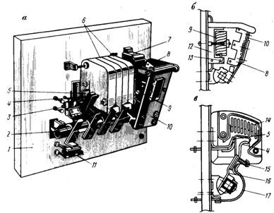 Three-pole KT contactor for a current of 400 A: a — general view (without arc groove on the first pole), b — electromagnet, c — contacts and arc groove, 1 — panel, 2 — shaft of movable contacts and armature, 3 — block contacts, 4 — main movable contact, 5 — fixed contact, B — arc chambers: 7 — electromagnetic core, 8 — armature, 9 — electromagnetic coil, 10 — armature holder, 11 — opening block contacts, 12 — core wire, 13 — short circuit, 14 — plates of the arc extinguishing chamber, 15 — contact spring, 16 — movable contact holder, 17 — flexible connection.
Unlike DC contactors, the switching mode of AC contactors is more severe than the off mode due to the inrush current of squirrel-cage induction motors. In addition, the presence of contact bounce when switching on leads to severe wear of the contacts under these conditions. So combating bounce when turned on is paramount here.