Losses and voltage drops - what are the differences
 In ordinary human life, the words "loss" and "fall" are used to denote the fact of a decrease in certain achievements, but they mean a different value.
In this case, «losses» means loss of a part, damage, reduction of the size of the previously achieved level. Losses are undesirable, but you can tolerate them.
The word "fall" is understood as a more serious harm associated with a complete deprivation of rights. Thus, even occasionally occurring losses (say, a portfolio) over time can lead to a decline (for example, the level of material life).
In this regard, we will consider this question in relation to the voltage of the electrical network.
How losses and voltage drops are formed
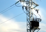
Electricity is carried over long distances by overhead lines from one substation to another.
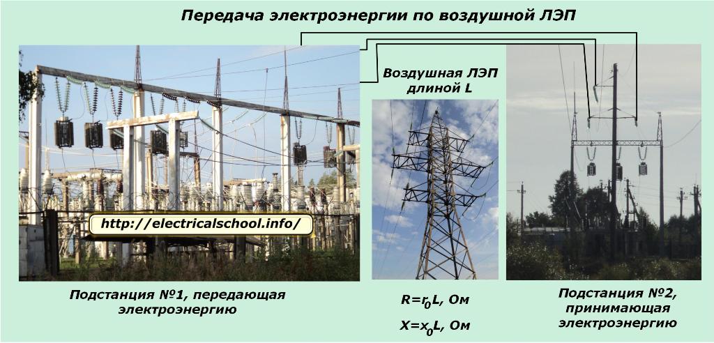
Overhead lines are designed to transmit the permissible power and are made of metal wires of a certain material and section. They create a resistive load with a resistance value of R and a reactive load of X.
On the receiving side it stands transformerelectricity conversion.Its coils have an active and pronounced inductive resistance XL. The secondary side of the transformer lowers the voltage and transmits it further to the consumers, whose load is expressed by the value of Z and is active, capacitive and inductive in nature. This also affects the electrical parameters of the network.
The voltage applied to the wires of the support of the overhead line, closest to the power transmission substation, overcomes the reactive and active resistance of the circuit in each phase and creates a current in it, the vector of which deviates from the vector of the applied voltage by an angle φ.
The nature of the distribution of voltages and the flow of currents along the line for a symmetrical load mode is shown in the photo.
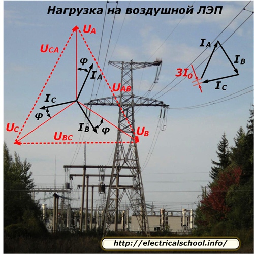
Since each phase of the line feeds a different number of consumers who are also randomly disconnected or connected to work, it is technically very difficult to perfectly balance the phase load. There is always an imbalance in it, which is determined by the vector addition of the phase currents and written as 3I0. In most calculations, it is simply ignored.
The energy consumed by the transmitting substation is partly spent in overcoming the resistance of the line and reaches the receiving side with little change. This fraction is characterized by loss and voltage drop, the vector of which decreases slightly in amplitude and is shifted by an angle in each phase.
How losses and voltage drop are calculated
In order to understand the processes taking place during the transmission of electricity, the vector form is convenient for representing the main characteristics. Various mathematical calculation methods are also based on this method.
To simplify the calculations in three-phase system it is represented by three single-phase equivalent circuits. This method works well with a symmetrical load and allows you to analyze the processes when it is broken.
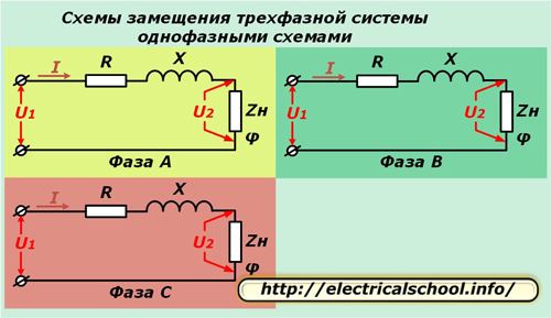
In the above diagrams, the active R and reactance X of each conductor of the line are connected in series with the complex load resistance Zn characterized by the angle φ.
In addition, calculation of voltage loss and voltage drop in one phase is performed. To do this, you need to specify the data. For this purpose, a substation is selected that receives energy, where the permissible load must already be determined.
The voltage value of any high-voltage system is already indicated in the reference books, and the resistances of the wires are determined by their length, cross-section, material and configuration of the network. The maximum current in the circuit is set and limited by the properties of the wires.
Therefore, to start the calculations, we have: U2, R, X, Z, I, φ.
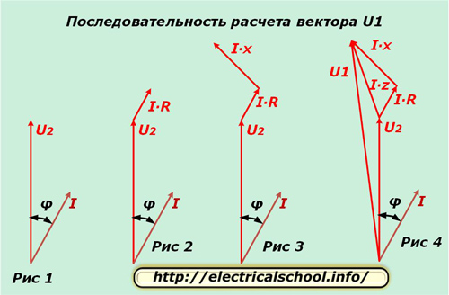
We take one phase, for example, «A» and separate for it in the complex plane the vectors U2 and I, displaced by an angle φ, as shown in Figure 1. The potential difference in the active resistance of the conductor coincides in direction with the current and in magnitude is determined from the expression I ∙ R. We postpone this vector from the end of U2 (Fig. 2).
The potential difference in the reactance of the conductor differs from the direction of the current by an angle φ1 and is calculated from the product I ∙ X. We postpone it from the vector I ∙ R (Fig. 3).
Reminders: for the positive direction of rotation of the vectors in the complex plane, the counterclockwise motion is taken. The current flowing through the inductive load lags the applied voltage by an angle.
Figure 4 shows the plotting of the potential difference vectors on the total wire resistance I ∙ Z and the voltage at the input of the circuit U1.
Now you can compare the input vectors to the equivalent circuit and across the load. To do this, put the resulting diagram horizontally (Fig. 5) and draw an arc from the beginning with the radius of the module U1 until it intersects with the direction of the vector U2 (Fig. 6).
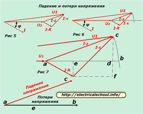
Figure 7 shows an enlargement of the triangle for greater clarity and the drawing of auxiliary lines, indicating the characteristic points of intersection with letters.
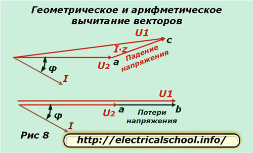
At the bottom of the picture it is shown that the resulting vector ac is called the voltage drop and ab is called the loss. They differ in size and direction. If we return to the original scale, we will see that ac is obtained as a result of geometric subtraction of vectors (U2 from U1), and ab is arithmetic. This process is shown in the picture below (Fig. 8).
Derivation of formulas for calculating voltage losses
Now let's go back to Figure 7 and notice that the bd segment is very small. For this reason, it is neglected in the calculations and the voltage loss is calculated from the segment length ad. It consists of two line segments ae and ed.
Since ae = I ∙ R ∙ cosφ and ed = I ∙ x ∙ sinφ, then voltage loss for one phase can be calculated by the formula:
∆Uph = I ∙ R ∙ cosφ + I ∙ x ∙ sinφ
If we assume that the load is symmetrical in all phases (conditionally neglecting 3I0), we can use mathematical methods to calculate the voltage loss in the line.
∆Ul = √3I ∙ (R ∙ cosφ + x ∙ sinφ)
If the right side of this formula is multiplied and divided by the network voltage Un, then we get a formula that allows us to perform pCalculation of voltage losses through the power supply.
∆Ul = (P ∙ r + Q ∙ x) / Un
The values of active P and reactive Q power can be taken from line meter readings.
Thus, the voltage loss in an electrical circuit depends on:
-
active and reactance of the circuit;
-
components of applied power;
-
the magnitude of the applied voltage.
Derivation of formulas for calculating the transverse component of the voltage drop
Let's go back to Figure 7. The value of the vector ac can be represented by the hypotenuse of a right triangle acd. We have already calculated the ad foot. Let us determine the transverse component cd.
The figure shows that cd = cf-df.
df = ce = I ∙ R ∙ sin φ.
cf = I ∙ x ∙ cos φ.
cd = I ∙ x ∙ cosφ-I ∙ R ∙ sinφ.
Using the obtained models, we perform small mathematical transformations and obtain the transverse component of the voltage drop.
δU = √3I ∙ (x ∙ cosφ-r ∙ sinφ) = (P ∙ x-Q ∙ r) / Un.
Determination of the formula for calculating the voltage U1 at the beginning of the power line
Knowing the value of the voltage at the end of the line U2, the loss ∆Ul and the transverse component of the drop δU, we can calculate the value of the vector U1 by the Pythagorean theorem. In expanded form, it has the following form.
U1 = √ [(U2 + (Pr + Qx) / Un)2+ ((Px-Qr) / Un)2].
Practical use
The calculation of voltage losses is carried out by engineers at the stage of creating an electric circuit project for the optimal selection of the configuration of the network and its constituent elements.
During the operation of electrical installations, if necessary, simultaneous measurements of the voltage vectors at the ends of the lines can be periodically carried out and the results obtained by the method of simple calculations can be compared. This method is suitable for devices that have increased requirements due to the need for high work accuracy.
Voltage losses in secondary circuits
An example is the secondary circuits of measuring voltage transformers, which sometimes reach several hundred meters in length and are transmitted by a special power cable with an increased cross-section.
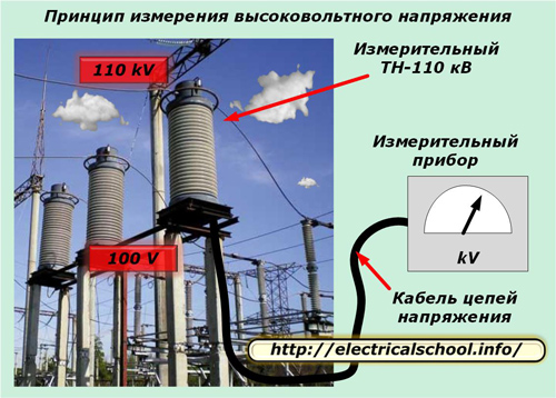
The electrical characteristics of such a cable are subject to increased requirements for the quality of voltage transmission.
Modern protection of electrical equipment requires the operation of measuring systems with high metrological indicators and an accuracy class of 0.5 or even 0.2. Therefore, losses of the voltage applied to them must be monitored and taken into account. Otherwise, the error introduced by them into the operation of the equipment can significantly affect all operational characteristics.
Voltage losses in long cable lines
The feature of the design of the long cable is that it has a capacitive resistance due to the fairly close arrangement of conducting cores and a thin layer of insulation between them. It further deflects the current vector passing through the cable and changes its magnitude.
The effect of voltage drop on capacitive resistance must be taken into account in the calculation to change the value of I ∙ z. Otherwise, the technology described above does not change.
The article provides examples of losses and voltage drops on overhead power lines and cables. However, they are found in all consumers of electricity, including electric motors, transformers, inductors, capacitor banks and other devices.
The amount of voltage losses for each type of electrical equipment is legally regulated in terms of operating conditions, and the principle of their determination in all electrical circuits is the same.