Parallel operation of generators
 In power plants, several turbo or hydraulic units are always installed, which work together in parallel on the common busbars of the generator or surge.
As a result, electricity production in power plants is produced by several generators working in parallel, and this cooperation has many valuable advantages.
Parallel operation of generators:
1. increases the flexibility of the operation of the equipment of power plants and substations, facilitates the preventive maintenance of the generators, the main equipment and the corresponding distribution devices with a minimum of the necessary reserve.
2. increases the efficiency of the operation of the power plant, as it enables the most efficient distribution of the daily load schedule between the units, thereby achieving the best use of electricity and increasing efficiency; in hydroelectric power plants, it makes it possible to use the power of the water flow to the maximum during the flood period and during the summer and winter low water periods;
3.increases the reliability and uninterrupted operation of power plants and power supply to consumers.
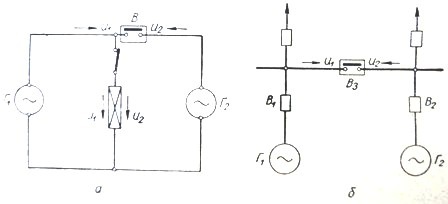
Rice. 1. Schematic diagram of parallel operation of generators
To increase production and improve power distribution, many power plants are combined to operate in parallel to form powerful power systems.
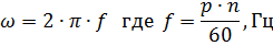
In normal operation, the generators are connected to common buses (generator or overvoltage) and rotate synchronously. Their rotors rotate at the same angular electrical speed
In parallel operation, the instantaneous voltages at the terminals of the two generators must be equal in magnitude and opposite in sign.
To connect the generator for parallel operation with another generator (or with the network), it is necessary to synchronize it, i.e. regulate the speed of rotation and excitation of the connected generator in accordance with the operating one.
Generators operating and connected in parallel must be in phase, that is, have the same order of phase rotation.
As can be seen from fig. 1, in parallel operation, the generators are connected to each other relative to each other, i.e. their voltages U1 and U2 on the switch will be exactly opposite. With respect to the load, the generators work in accordance, that is, their voltages U1 and U2 match. These conditions of parallel operation of the generators are reflected in the diagrams of fig. 2.
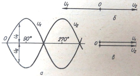
Rice. 2. Conditions for turning on generators for parallel operation. The generator voltages are equal in magnitude and opposite in phase.
There are two methods of synchronizing generators: fine synchronization and coarse synchronization or self-synchronization.
Conditions for exact synchronization of generators.
With precise synchronization, the excited generator is connected to the network (buses) through switch B (Fig. 1) upon reaching synchronization conditions — equality of the instantaneous values of their voltages U1 = U2
When the generators operate separately, their instantaneous phase voltages will be equal, respectively:


This implies the conditions necessary for the parallel connection of the generators. For generators on and running, it is required:
1. equality of the effective voltage values U1 = U2
2. equality of angular frequencies ω1 = ω2 or f1 = f2
3. matching of voltages in phase ψ1 = ψ2 or Θ = ψ1 -ψ2 = 0.
The exact fulfillment of these requirements creates ideal conditions, which are characterized by the fact that at the moment of switching on the generator, the stator equalization current will be zero. It should be noted, however, that the fulfillment of the conditions for exact synchronization requires careful adjustment of the compared values of the voltage, frequency and phase angles of the voltage of the generators.
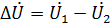
In this regard, it is practically impossible to fully fulfill the ideal conditions for synchronization; they are performed approximately, with some slight deviations. If one of the above conditions is not met, when U2, the voltage difference will act on the terminals of the open communication switch B:
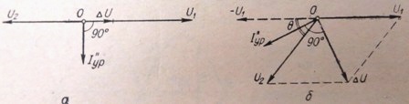
Rice. 3. Vector diagrams for cases of deviation from the conditions of exact synchronization: a — The working voltages of the generators are not equal; b — angular frequencies are not equal.
When the switch is turned on, under the action of this potential difference in the circuit will flow an equalizing current, the periodic component of which at the initial moment will be
Consider two cases of deviation from the exact synchronization conditions shown in the diagram (Fig. 3):
1. the operating voltages of the generators U1 and U2 are not equal, the other conditions are met;
2. the generators have the same voltage but rotate at different speeds, that is, their angular frequencies ω1 and ω2 are not equal and there is a phase mismatch between the voltages.
As can be seen from the diagram in fig. 3, a, the inequality of the effective values \u200b\u200bof the voltages U1 and U2 causes the appearance of an equalizing current I ”ur, which will be almost purely inductive, since the active resistances of the generators and connecting wires of the network are very small and are neglected. This current creates no active power surges and therefore no mechanical stresses in the generator and turbine parts. In this regard, when the generators are switched on for parallel operation, the difference in voltage can be allowed up to 5-10%, and in emergency cases - up to 20%.
When the rms voltage values U1 = U2 are equal, but when the angular frequencies differ Δω = ω1 — ω2 ≠ 0 or Δf = f1 — f2 ≠ 0, the voltage vectors of the generators and the network (or of the 2nd generator) are shifted with a certain angle Θ that changes over time. The voltages of the generators U1 and U2 in this case will differ in phase not by an angle of 180 °, but by an angle of 180 ° —Θ (Fig. 3, b).
At the terminals of the open switch B, between points a and b, the voltage difference ΔU will act. As in the previous case, the presence of voltage can be detected using a light bulb, and the rms value of this voltage can be measured with a voltmeter connected between points a and b.
If the switch B is closed, then under the action of the voltage difference ΔU, an equalizing current I ” occurs, which in relation to U2 will be almost purely active and, when the generators are turned on in parallel, will cause shocks and mechanical stresses in the shafts and other parts of the generator and the turbine.
At ω1 ≠ ω2, the synchronization is completely satisfactory if the slip is s0 <0, l% and the angle Θ ≥ 10 °.
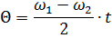
Due to the inertia of the turbine regulators, it is impossible to achieve a long-term equality of the angular frequencies ω1 = ω2, and the angle Θ between the voltage vectors, characterizing the relative position of the stator and rotor windings of the generators, does not remain constant, but changes continuously; its instantaneous value will be Θ = Δωt.
On the vector diagram (Fig. 4), the last circumstance will be expressed in the fact that with a change in the phase angle between the voltage vectors U1 and U2, ΔU will also change. The voltage difference ΔU in this case is called the shock voltage.
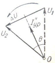
Rice. 4. Vector diagram of generator synchronization with frequency inequality.
The instantaneous value of the clock voltages Δu is the difference between the instantaneous values of the voltages u1 and u2 of the generators (Fig. 5).
Suppose that the equality of effective values U1 = U2 is achieved, the phase angles of the reference time ψ1 and ψ2 are also equal.
Then you can write
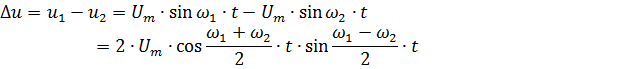
The shock stress curve is shown in Fig. 5.
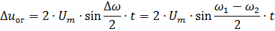
The rhythm voltage changes harmonically with a frequency equal to half the sum of the compared frequencies and with an amplitude that varies with time depending on the phase angle Θ:
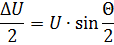
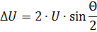
From the vector diagram in fig.4, for a certain specified value of the angle Θ, the effective value of the impact stress can be found:
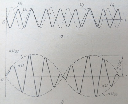
Rice. 5. Curves of overcoming stress.
Taking into account the change of the angle Θ over time, it is possible to write an expression for the shell in terms of the shock stress amplitudes, which gives the change in the stress amplitudes over time (the dotted curve in Fig. 5, b ):
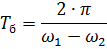
As can be seen from the vector diagram in Fig. 4 and the last equation, the shock stress amplitude ΔU varies from 0 to 2 Um. The largest value of ΔU will be at the moment when the voltage vectors U1 and U2 (Fig. 4) coincide in phase and angle Θ = π, and the smallest — when these voltages differ in phase by 180 ° and angle Θ = 0. The period of the rhythm curve is equal to
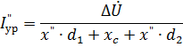
When the generator is connected for parallel operation with a powerful system, the value of xc of the system is small and can be neglected (xc ≈ 0), then the equalizing current
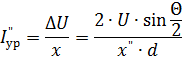
and the inrush current
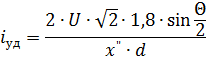
In the case of unfavorable switching on at the current Θ = π, the surge current in the stator winding of the switched-on generator can reach twice the value of the surge voltage of a three-phase short circuit of the generator terminals.
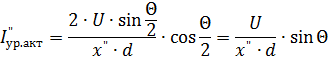
The active component of the equalizing current, as can be seen from the vector diagram in Fig. 4 is equal to