Switching in DC machines
 Switching in DC machines is understood as phenomena caused by a change in the direction of the current in the wires of the armature winding when they move from one parallel branch to another, that is, when crossing the line along which the brushes are located ( from the Latin commulatio — change). Let us consider the commutation phenomenon using the example of a ring armature.
In fig. 1 shows a scan of part of the armature winding consisting of four wires, part of the collector (two collector plates) and a brush. Wires 2 and 3 form a switched loop, which in fig. 1, a is shown in the position it occupies before switching, in fig. 1, c — after switching, and in fig. 1, b — during the switching period. The collector and armature winding rotate in the direction indicated by the arrow with a speed of rotation n, the brush is stationary.
At the moment before switching, the armature current Iya passes through the brush, the right collector plate and is divided in half between the parallel branches of the armature winding. Wires 1, 2 and 3 and wire 4 form different parallel branches.
After switching, wires 2 and 3 switched to another parallel branch, and the direction of the current in them changed to the opposite. This change occurred in a time equal to the switching period Tk, i.e. in the time it takes the brush to move from the right plate to the adjacent left (actually the brush overlaps several collector plates at once, but in principle this does not affect the switching process) ...
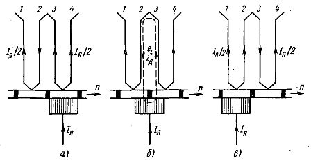
Rice. 1. Diagram of the current switching process
One of the moments of the switching period is shown in Fig. 1, b. The circuit to be switched turns out to be a short circuit from the collector plates and the brush. Since during the commutation period there is a change in the direction of the current in the loop 2-3, this means that an alternating current flows through the loop, creating an alternating magnetic flux.
The latter induces e. In the switched loop. etc. v. self-induction eL or reactive e. etc. v. According to Lenz's principle, e.g. etc. c. self-induction tends to keep the current in the wire in the same direction. Therefore, the direction of eL coincides with the direction of the current in the loop before switching.
Under the influence of e. etc. c. self-induction in short-circuit 2-3, a large additional current id flows, since the loop resistance is small. At the point of contact of the brush with the left plate, the id current is directed against the armature current, and at the point of contact of the brush with the right plate, the direction of these currents coincides.
The closer to the end of the switching period, the smaller the contact area of the brush with the right plate and the higher the current density. At the end of the switching period, the brush contact with the right plate is broken and an electric arc is formed.The higher the current ID, the more powerful the arc.
If the brushes are located on the geometric neutral, then in the switched circuit the magnetic flux of the armature induces e. etc. v. rotation of Hebr. In fig. 2 shows on an enlarged scale the conductors of the switched loop located on the geometric neutral and the direction of e. etc. c. self-inductance eL for the generator coinciding with the direction of the armature current in this wire before switching.
The direction of Heb is determined by the right-hand rule and always coincides with the direction of eL. As a result, the id increases even more. The resulting electric arc between the brush and the collector plate can destroy the surface of the collector, resulting in poor contact between the brush and the collector.
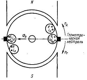
Rice. 2. Direction of electromotive force in the commutation loop
To improve switching conditions, the brushes are shifted to physical neutrality. When the brushes are located on the physical neutral, the included coil does not cross an external magnetic flux and e. etc. v. rotation is not induced. If you move the brushes beyond physical neutrality as shown in fig. 3, then in the switched loop the resulting magnetic flux will induce e. etc. with ek, the direction of which is opposite to the direction of e. etc. v. self-induction eL.
In this way, not only e. It will be compensated. etc. v. rotation, but also e. etc. v. self-induction (partially or completely). As mentioned earlier, the shear angle of the physical neutral changes all the time, and therefore the brushes are usually mounted offset at some average angle to it.
Reduction of e. etc. within the included loop leads to a decrease in the current id and a weakening of the electric discharge between the brush and the collector plate.
It is possible to improve the switching conditions by installing additional poles (Ndp and Sdn in Fig. 4). The additional pole is located along the geometric neutral. For generators, the additional pole of the same name is located behind the main pole in the direction of rotation of the armature, and for the motor - vice versa. The windings of the additional poles are connected in series with the armature winding in such a way that the flux Fdp created by them is directed to the armature flux Fya.
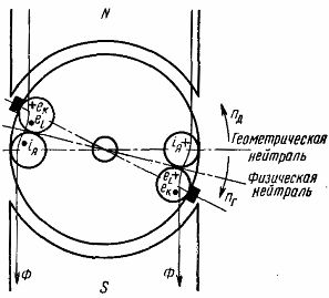
Rice. 3. The direction of the electromotive force in the switching loop when the brushes are moved beyond the physical neutral
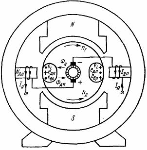
Rice. 4. Circuit diagram of the windings of the additional poles
Since both fluxes are created by a single current (armature current), it is possible to choose the number of turns of the winding of the additional poles and the air gap between them and the armature so that the fluxes are equal in value at each armature current . The auxiliary pole flux will always compensate the armature flux and thus e. etc. v. there will be no rotation in the switched loop.
The additional poles are usually made so that their flux induces e in the switched circuit. d. s equal to the sum eL + Heb. Then at the moment of separation of the brush from the right collector plate (see Fig. 1, c) the electric arc does not occur.
Industrial direct current machines with a power of 1 kW and more are equipped with additional poles.