The selection of starting rheostats for asynchronous motors
 Asynchronous electric motors with a phase rotor are started by means of rheostats included in the rotor circuit of the electric motor. The following are used as starting rheostats for the indicated circuit:
1. Normal manual starting rheostats,
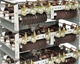
2. contactor rheostats which are sets of normalized resistance boxes complete with magnetic control stations.
To choose starting rheostats for asynchronous motors with a wound rotor, you need to know:
1. power that the rheostat must absorb at start-up,
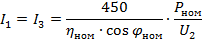
2. the ratio U2 / I2, where U2 is the voltage between the rotor rings when the rotor is stationary, when the stator is switched on at rated voltage at rated frequency, and I2 is the rated current in the rotor phase,
3. the frequency of starts per hour, assuming that the starts follow each other consecutively at intervals equal to twice the start time,
4. number of rheostat steps.
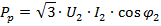
The power absorbed by the rheostat at startup is equal to:
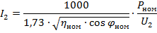
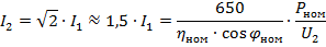
The ring voltage and rated rotor current are specified in electric motor catalogs. In the absence of data, the value of the current I2 can be determined using the following approximate formulas:
1. three-phase rotor
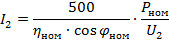
or
where Pnom is the nominal power of the electric motor, kW, ηnom is the nominal efficiency of the electric motor, cosφnom is the power factor (nominal value),
2. two-phase rotor, current in two outer rings:
3. the same, but the current in the middle ring:
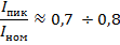
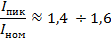
As stated above, normal design control rheostats are available for the following modes:
-
starting with half load (or no load) — at half torque,
-
start at full load — at full torque,
-
overload start — with double torque.
The starting (peak) current of the rheostat relative to the nominal is:
for case «a»
for case «b»
for case "c"
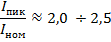
Table 1 shows approximate practical data for the selection of starting rheostats for asynchronous electric motors with a wound rotor… For an approximate determination of the required stages of the rheostat, you can use the table. 2.
Table 1 Determination of the resistance value of the rheostat
Ratio U2 / I2 Rheostat resistance, ohm (per phase) Permissible current, A 0.42-0.75 0.734 280—140 0.75—1.3 1.11 180—87.4 1.3—2.4 2.00 136-64 2.4-4.2 2.88 100-150 4.2-7.5 4.50 76-47
Table 2 Recommended number of steps for starting resistors
Power, kWt Number of steps of starting resistances per phase with manual control with contactor control full load half load fans or centrifugal pumps 0.75—2.5 2 1 1 1 3.5—7.8 2 2 2 2 10-20 2 2 1 2 22—35 3 2 2 2 35—55 3 3 2 3 60—95 4 4 3 3 100—200 4 5 3 4 220-370 4 6 4 5
With a high starting frequency and, if necessary, remote control of the motor, conventional manual rheostats are unsuitable. In this case, contact rheostats are used.