Unbranched and branched linear electrical circuits with a single supply
 If a large number of passive elements together with a source of e. etc. c. form an electric circuit, their interconnection can be done in different ways. There are the following typical schemes for such connections.
Serial connection of elements This is the simplest connection. With this connection, the same current flows in all elements of the circuit. According to this scheme, either all the passive elements of the circuit can be connected, and then the circuit will be single-circuit unbranched (Fig. 1., a), or only part of the elements of the multi-circuit circuit can be connected.
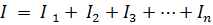
If n elements are connected in series in which the same current I flows, then the voltage at the terminals of the circuit will be equal to the sum of the voltage drops in n elements connected in series, i.e.
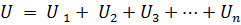
or:

where Rek is the equivalent circuit resistance.
Therefore, the equivalent resistance of passive elements connected in series is equal to the sum of the resistances of these elements... The electrical scheme (Fig.1, a) an equivalent circuit can be presented (Fig. 1, b), consisting of one element with an equivalent resistance Rek
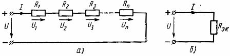
Rice. 1. Scheme of serial connection of linear elements (a) and its equivalent scheme (b)
When calculating a circuit with elements connected in series at a given voltage of the power source and resistances of the elements, the current in the circuit is calculated according to Ohm's law:

Voltage drop across the kth element
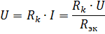
depends not only on the resistance of this element, but also on the equivalent resistance Rek, that is, on the resistance of other elements of the circuit. This is a significant disadvantage of serial connection of elements. In the limiting case, when the resistance of any element of the circuit becomes equal to infinity (open circuit), the current in all elements of the circuit becomes zero.
Since, when connected in series, the current in all elements of the circuit is the same, the ratio of the voltage drop in the elements is equal to the ratio of the resistances of these elements:

Parallel connection of elements — this is a connection in which the same voltage is applied to all elements of the circuit. According to the parallel connection scheme, either all passive elements of the circuit (Fig. 2, a) or only part of them can be connected. Each parallel connected element forms a separate branch. Therefore, the circuit with parallel connection of elements shown in Fig. 2, a, although it is a simple circuit (since it contains only two nodes), it is at the same time branched.
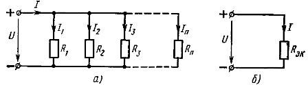
Rice. 2. Scheme of parallel connection of linear elements (a) and its equivalent scheme (b)
In each parallel branch, the current
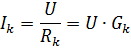
where Gk is the conductivity of the kth branch.
or

where Gec is the equivalent circuit conductance.
Therefore, when passive elements are connected in parallel, their equivalent conductance is equal to the sum of the conductances of these elements... The equivalent conductance is always greater than the conductance of any part of the parallel branches. Equivalent conductivity GEK corresponds to equivalent resistance Rek = 1 / Gek.
Then the equivalent circuit shown in Fig. 2, a, will have the form shown in fig. 2, b. The current in the unbranched part of the circuit with parallel connection of elements can be determined from this circuit according to Ohm's law:
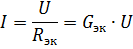
Therefore, if the supply voltage is constant, then with an increase in the number of elements connected in parallel (which leads to an increase in the equivalent conductivity), the current in the unbranched part of the circuit (the power supply current) increases.
From the formula

it can be seen that the current in each branch depends only on the conductance of that branch and does not depend on the conductance of other branches. The independence of parallel branch modes from each other is an important advantage of parallel connection of passive elements. In industrial installations, parallel connection of electrical receivers is used in most cases. The most obvious example is the inclusion of electric lamps for lighting.
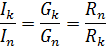
Since in a parallel connection the same voltage is applied to all elements and the current in each branch is proportional to the conductance of that branch, the ratio of currents in parallel branches is equal to the ratio of the conductances of these branches, or inversely proportional to the ratio of their resistances:
A mixed connection of elements is a combination of series and parallel connections. Such a chain can have a different number of nodes and branches. An example of a mixed connection is shown in the diagram (Fig. 3, a)
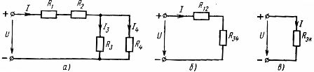
Rice. 3. Scheme of mixed connection of linear elements (a) and its equivalent schemes (b, c).
To calculate such a circuit, it is necessary to successively determine the equivalent resistances for those parts of the circuit that are only series or only parallel connection. In the considered circuit, there is a series connection of elements with resistances R1 and R2 and a parallel connection of elements with resistances R3 and R4. Using the previously obtained relationships between the parameters of the circuit elements with their series and parallel connection, the real electrical circuit can be successively replaced by equivalent circuits.
Equivalent resistance of elements connected in series

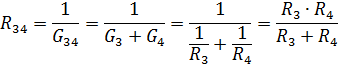
Equivalent resistance of parallel connected elements R3 and R4
An equivalent circuit with the resistances of the elements R12 and R34 is shown in Fig. 3, b. For this series connection of R12 and R34, the equivalent resistance is

and the corresponding equivalent circuit is shown in Fig. 2, b. Let's find the current in this circuit:

These are the supply current and the current in the elements R1 and R2 of the real circuit.To calculate the currents I3 and I4, determine the voltage in the section of the circuit with resistance R34 (Fig. 3, b):

Then the currents I3 and I4 can be found according to Ohm's law:


In a similar way, you can calculate a number of other electrical circuits with mixed connection of passive elements.
For complex circuits with a large number of circuits and sources of e. etc. c. such an equivalent conversion cannot always be carried out. They are calculated by other methods.