DC circuit breakers
 DC circuit breakers are used to disconnect a circuit under load. At traction substations, switches are used to disconnect 600 V power lines during overload and short-circuit currents and to disconnect the reverse current of rectifiers during back-ignition or valve failure (i.e. internal short-circuits during of parallel block operation).
Arc extinguishing by automatic switches occurs in the air on arc horns. Arc extension can be done using a magnetic blast or in narrow slot chambers.
In all cases of disconnection of the circuit and the formation of an electric arc, a natural upward movement of the arc occurs along with the movement of the air heated by it, i.e.
On traction substations mainly applied to high-speed circuit breakers.
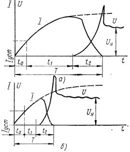
Rice. 1. Oscillograms of current and voltage when the short-circuit current is turned off: a-fast switch, b-high-speed switch
The total time T of interruption of the short-circuit or overload current by the circuit-breaker consists of three main parts (Fig. 1):
T = tO + t1 + t2
where t0 is the time of rise of the current in the circuit to be switched off to the value of the setting current, i.e. to the value at which the disconnecting device of the circuit breaker is actuated; t1 is the opening time of the own circuit breaker, i.e. the time from the moment the setting current is reached to the moment the breaker contacts begin to diverge; t2 — arc burning time.
The rise time of the current in the circuit t0 depends on the parameters of the circuit and the setting of the switch.
The internal trip time t1 depends on the switch type: for non-high-speed switches, the internal trip time is in the range 0.1-0.2 s, for high-speed switches - 0.0015-0.005 sec.
The arcing time t2 depends on the value of the current to be interrupted and on the characteristics of the circuit breakers.
The total trip time of the high-speed breaker is within 0.15-0.3s, for the high-speed-0.01-0.03s.
Due to the short inherent tripping time, the high-speed circuit breaker limits the maximum value of the short-circuit current in the protected circuit.
At traction substations, high-speed DC automatic circuit breakers are used: VAB-2, AB-2/4, VAT-43, VAB-20, VAB-20M, VAB-28, VAB-36 and others.
Switch VAB-2 is polarized, that is, it responds to current in only one direction — forward or reverse, depending on the setting of the switch.
In fig. 2 shows the electromagnetic mechanism of the DC circuit breaker.
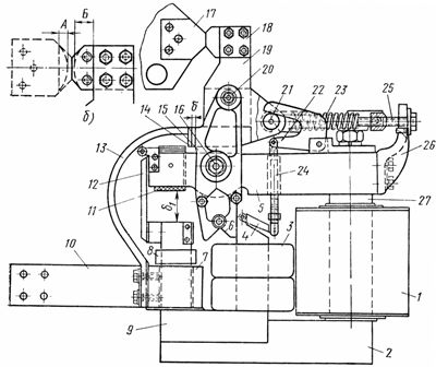
Rice. 2.Electromagnetic mechanism of the circuit breaker VAB -2: a — disconnection of the circuit breaker, b — limits of limit wear of the contacts of the circuit breaker VAB -2, (A — the minimum thickness of the fixed contact is 6 mm, B — the minimum thickness of the movable contact is 16 mm ); 1 — holding coil, 2 — magnetic circuit, 3 — switching coil, 4 — magnetic armature, 5 — upper steel rail, 6 — anchor, 7 — main coil, 8 — calibration coil, 9 — U-shaped magnetic circuit, 10 — current current output, 11 — adjusting screw, 12 — maneuvering plate, 13 — flexible connection, 14 — stop, 15 — armature lever, 16 — axis of armature lever, 17 — fixed contact, 18 — movable contact, 19 — contact lever, 20 — axial contact lever, 21 — axle with roller, 22 — locking lever, 23 — closing springs, 24 — drawbar, 25 — adjusting screws, 26 — bracket, 27 — holding coil core
The anchor lever 15 (Fig. 2, a) rotates around the axis 16 passing through the upper steel rod 5. In the lower part of the lever 15, consisting of two silimin cheeks, a steel anchor 6 is tightened, and in the upper part there is a spacer a sleeve with an axis 20 around which the contact lever 19 rotates, made of a set of duralumin plates.
A movable contact 18 is fixed in the upper part of the contact lever, and a copper shoe with a flexible connection 13 is fixed below, with the help of which the movable contact is connected to the main current coil 7 and through it to the terminal 10. To the lower part of the contact lever, stops 14 are attached on both sides, and on the right side there is a steel axle with a roller 21, to which two closing springs 23 are attached on one side.
In the off position, the system of levers (armature lever and contact lever) is rotated by the stop springs 23 about the axis 16 until the armature 6 stops in the left rod of the U-shaped magnetic circuit.
The closing 3 and holding 1 coils of the circuit breaker are powered by their own DC requirements.
To turn on the switch, you must first close the circuit of the holding coil 1, then the circuit of the closing coil 3. The direction of the current in both coils should be such that the magnetic fluxes generated by them add to the right core of the magnetic circuit 9, which serves as the core of the closing coil; then the armature 6 will be attracted to the core of the closing coil, that is, it will be in the «On» position. In this case, the axis 20 together with the contact lever 19 will rotate to the left, the decoupling springs 23 will stretch and tend to rotate the contact lever 19 around the axis 20.
When the switch is off, the armature 4 rests on the end side of the closing coil and, when the switch is on, remains attracted to the core end by the common magnetic flux of the closing and holding coils. The magnetic armature 4 by means of a rod 24 is connected to the locking lever 22, which does not allow the contact lever to rotate to the limiter of the movable contact in the fixed one. Therefore, a gap remains between the main contacts, which can be adjusted by changing the length of the rod 24 and should be equal to 1.5-4 mm.
If the voltage is removed from the closing coil, then the electromagnetic forces holding the armature 4 in the attracted position will reduce and the springs 23 with the help of the locking lever 22 and the rod 24 will tear the armature from the end of the core of the closing coil and rotate the contact lever until the main contacts close. Therefore, the main contacts will close only after the closing coil opens.
In this way, the principle of free tripping is realized for VAB-2 circuit breakers. The gap between the magnetic armature 4 (otherwise called the free trip armature) and the end side of the closing core of the coil in the on position of the switch should be within 1.5-4mm.
The control circuit ensures the supply of a short-term pulse of current to the closing coil, the duration of which is sufficient only to have time to move the armature to the «On» position. The closing coil circuit then opens automatically.
The presence of a free trip can be checked as follows. A sheet of paper is placed between the main contacts and the contactor contact is closed. The circuit breaker is turned on, but while the contactor contact is closed, the main contacts should not be closed, and the paper can be freely removed from the gap between the contacts. As soon as the contactor of the contactor opens, the magnetic armature will break away from the core end of the closing coil and the main contacts will close. In this case, the piece of paper will be pressed between the contacts and it will not be possible to remove it.
When the switch is turned on, a characteristic double bang is heard: the first is from the collision of the armature and the core of the closing coil, the second is from the collision of the closed main contacts.
The polarization of the switch consists in choosing the direction of the current in the holding coil, depending on the direction of the current in the main current coil.
In order for the switch to turn off the circuit when the direction of the current in it changes, the direction of the current in the holding coil is chosen so that the magnetic fluxes created by the holding coil and the main current coil coincide in direction in the core of the closing coil. Therefore, when the current flows in the forward direction, the main circuit current will help to keep the circuit breaker in the closed position.
In emergency mode, when the direction of the main current is reversed, the direction of the magnetic flux created by the main current coil in the core of the closing coil will change, i.e. the magnetic flux of the primary current coil will be directed against the magnetic flux of the holding coil and at a certain value of primary current the core of the closing coil will be demagnetized and the opening springs will open the breaker. The speed of response is determined to a greater extent by the fact that while in the core of the switching coil the magnetic flux decreases, in the core of the main current coil the magnetic flux increases.
In order for the switch to turn off the circuit when the current increases above the set forward current, the direction of the current in the holding coil is chosen so that the magnetic flux of the holding coil in the core of the closing coil is directed against the magnetic flux of the main current coil, when the forward current flows through it.In this case, as the base current increases, the demagnetization of the closing coil core increases, and at a certain value of the base current, equal to or higher than the setting current, the breaker opens.
The tuning current in both cases is adjusted by changing the current value of the holding coil and by changing the gap δ1.
The magnitude of the holding coil current is adjusted by varying the magnitude of the additional resistance connected in series with the coil.
Changing the gap δ1 changes the magnetic flux resistance of the primary current coil. As the gap δ1 decreases, the magnetic resistance decreases and therefore the magnitude of the breaking current decreases. The gap δ1 is changed using the adjusting screw 11.
The distance δ2 between the stops 14 and the cheeks of the armature lever 15 in the on position of the switch characterizes the quality of closing the main contacts and should be within 2-5 mm. The plant produces keys with a gap δ2 equal to 4-5 mm. The size of the gap δ2 determines the angle of rotation of the contact lever 19 about the axis 20.
The absence of a gap δ2 (stops 14 are in contact with the cheeks of the armature lever 15) indicates poor contact or lack of contact between the main contacts. A distance δ2 less than 2 or more than 5 mm indicates that the main contacts are in contact only at the lower or upper edge. The difference δ2 can be small due to the high wear of the contacts, which are then replaced.
If the dimensions of the contacts are sufficient, then the gap δ2 is adjusted by moving the entire switching mechanism along the circuit breaker frame.To move the mechanism, two bolts are released that fix the mechanism to the frame.
The distance between the main contacts in the open position should be equal to 18-22 mm. The pressing of the main contacts for switches with a rated current up to and including 2000 A should be in the range of 20-26 kg, and for switches with a rated current of 3000 A - within 26-30 kg.
In fig. 2, b shows the movable system of the switch with the designation of the wear limit of the contacts. The movable contact is considered worn when dimension B becomes less than 16 mm, and the fixed contact when dimension A becomes less than 6 mm.
In fig. 3 shows a detailed control scheme of the VAB-2 circuit breaker. The scheme ensures the supply of a short-term pulse to the closing coil and does not allow repeated switching on when the power button is pressed for a long time, i.e. prevents "ringing". The holding coil is continuously charged with current.
To turn on the switch, press the «On» button, thereby closing the circuit of the coils of the contactor K and the blocking RB. In this case, only the contactor that closes the circuit of the closing coil VK is activated.
As soon as the armature takes the «On» position, the closing auxiliary contacts of the BA breaker will close and the opening contacts will open. One of the auxiliary contacts bypasses the coil of contactor K, which will break the circuit of the closing coil. In this case, the entire line voltage will be applied to the coil of the RB blocking relay, which, after actuation, again manipulates the contactor coil with its contacts.
To close the switch again, open the power button and close it again.
The discharge resistance CP connected in parallel with the DC holding coil serves to reduce the open circuit overvoltage of the coil. The adjustable LED resistance provides the ability to vary the holding coil current.
The rated current of the holding coil at 110 V is 0.5 A, and the rated current of the closing coil at the same voltage and parallel connection of the two sections is 80 A.
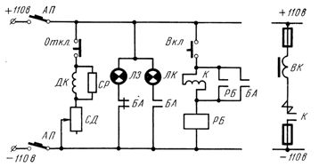
Rice. 3. Wiring diagram for circuit breaker control VAB-2: Off. — off button, DC — holding coil, LED — additional resistance, CP — discharge resistance, BA — switch auxiliary contacts, LK, LZ — red and green signal lamps, Incl. — power button, K — contactor and its contact, RB — blocking relay and its contact, VK — closing coil, AP — automatic switch
Fluctuations in the voltage of the working circuits are permissible from - 20% to + 10% of the nominal voltage.
The total time to disconnect the circuit from the VAB-2 circuit breaker is 0.02-0.04 sec.
The extinguishing of the arc, when the circuit breaker breaks the circuit under load, occurs in the arc chute by means of a magnetic burst.
The magnetic inflator coil is usually connected in series with the main fixed contact of the switch and is a turn of the main busbar, inside which there is a core made of steel strip. In order to concentrate the magnetic field in the arcing zone in the contacts, the core of the magnetic explosion coil in the switches has pole pieces.
The arc extinguishing chamber (Fig. 4) is a flat box made of asbestos cement, inside which two longitudinal partitions 4 are made. A horn 1 is installed in the chamber, inside which the axis of rotation of the chamber passes.This horn is electrically connected to the movable contact. Another horn 7 is fixed on a stationary contact. To ensure a quick transition of the arc from the movable contact to horn 1, the distance of the horn from the contact should be no more than 2-3 mm.
The electric arc that occurs when switching off between contacts 2 and 6 under the action of a strong magnetic field of the magnetic inflator coil 5 is quickly blown over the horns 1 and 7, lengthened, cooled by the counterflow of air and the walls of the chamber in narrow slots between partitions and are quickly extinguished. It is recommended to place ceramic tiles in the chamber walls in the arc extinguishing area.
Arc extinguishing chambers for circuit breakers for voltages of 1500 V and more (Fig. 5) differ from chambers for voltages of 600 V in large dimensions and the presence of holes in the outer walls for the exit of gases and an additional device for magnetic detonation.
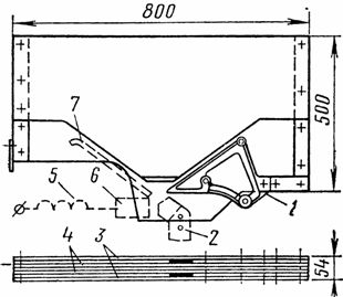
Rice. 4. Arc extinguishing chamber of the circuit breaker VAB -2 for a voltage of 600 V: 1 and 7 — horns, 2 — movable contact, 3 — outer walls, 4 — longitudinal partitions, 5 — magnetic explosion coil, 6 — fixed contact
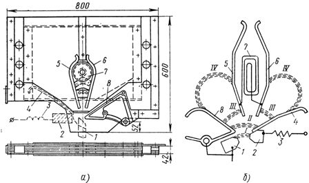
Rice. 5. Chamber for arc extinguishing of circuit breaker VAB -2 for a voltage of 1500 V: a — camera chamber, b — arc extinguishing circuit with an additional magnetic burst; 1 — movable contact, 2 — fixed contact, 3 — magnetic detonating coil, 4 AND 8 — horns, 5 and 6 — auxiliary horns, 7 — auxiliary magnetic detonating coil, I, II, III, IV — arc position during extinguishing
The device for additional magnetic blowing consists of two auxiliary horns 5 and 6, between which the coil 7 is connected. As the arc is extended, it begins to close through the auxiliary horns and the coil, which, due to the current flowing through it, creates an additional magnetic shock. All cameras have metal tiles on the outside.
For fast and stable arc extinction, the gap between the contacts should be at least 4-5 mm.
The body of the switch is made of a non-magnetic material - silymine - and is connected to a movable contact, so during operation it is under full working voltage.
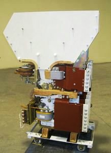
BAT-42 Automatic High Speed DC Switch
Operation of DC Circuit Breakers
During operation, it is necessary to monitor the condition of the main contacts. The voltage drop between them at nominal load should be within 30 mV.
The oxide is removed from the contacts with a wire brush (brushing). When sagging occurs, they are removed with a file, but the contacts should not be fed to restore their original flat shape, as this leads to their rapid wear.
It is necessary to periodically clean the walls of the arc extinguishing chamber from copper and coal deposits.
When revising a DC switch, the insulation of the holding and closing coils with respect to the body is checked, as well as the insulation resistance of the walls of the arcing chamber. The isolation of the arc chamber is checked by applying voltage between the main movable and fixed contacts with the chamber closed.
Before putting the switch into operation after repair or long-term storage, the chamber must be dried for 10-12 hours at a temperature of 100-110 ° C.
After drying, the chamber is mounted on the switch and the insulation resistance is measured between the two points of the chamber opposite the movable and fixed contacts when they are open. This resistance must be at least 20 ohms.
The circuit breaker settings are calibrated in a laboratory with current obtained from a low voltage generator with a nominal voltage of 6-12 V.
At the substation, circuit breakers are calibrated with load current or using a load rheostat at a nominal voltage of 600 V. A method for calibrating DC switches can be recommended using a calibration coil of 300 turns of PEL wire with a diameter of 0.6 mm, mounted on the core of the main current coil. By passing a direct current through the coil, the value of the current setting is set according to the number of ampere-turns at the time the switch is turned off. The switches of the first version, which were produced earlier, differ from the switches of the second version by the presence of an oil valve.