Receiver Terminal Voltage Regulation Circuits
 Incandescent lamps, heating devices, electrolysis baths, electric motors, etc. They can be used as receivers of electrical energy in direct current circuits. At relatively low powers, voltage and current are regulated using variable resistors - rheostats.
In the simplest case, a rheostat can be connected in series with the receiver... When the resistance of the rheostat changes, the current I and the voltage Upr at the terminals of the receiver change (Fig. 1, a). Such a circuit can serve to regulate current and voltage within relatively narrow limits.
If regulation of voltage Upr and current Ipr of the receiver is required within wide limits at a constant voltage in the network, then a potentiometer circuit is applied (Fig. 1.6).
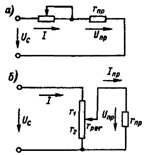
Rice. 1. Circuits for regulating the voltage of the receiver terminals: a — with sequential inclusion of the rheostat, b — potentiometer circuit
The resistance of the rheostat greg is chosen several times lower than the resistance of the receiver, which with conventional equipment is possible for low-power receivers. If rpr rreg, then with some error for small currents of the receiver, the voltage Unp at its terminals is determined as
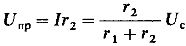
The receiver terminal voltage will change in direct proportion to the displacement of the movable contact — it will depend linearly on the displacement. If we take into account the receiver current, which increases with increasing voltage UNSp, then this dependence will be non-linear.
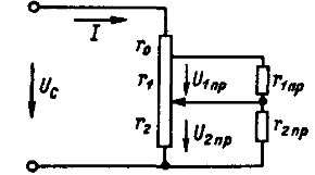
Rice. 2. Schematic regulation of the voltage in the terminals of the receiver - voltage divider
If one or several different supply voltages to the receivers are required at a constant mains voltage Uc, then voltage divider circuitshown in fig. 2… If the resistances of sections r1 and r2 are relatively small compared to the resistances r1pr and r2pr, we get
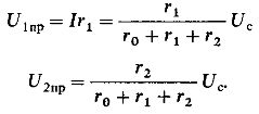
At significant powers, the devices are used as voltage dividers, in which energy losses are relatively small.