Resistor bridge circuit and its application
 In electrical measurements, as in some other cases, resistors are included according to the electrical bridge circuit or bridge circuit (Fig. 1, a).
Resistors with resistances R1, R2, R3, R4 form the so-called bridge arms. The sections of the connecting points a and in the circuit, as well as b u d, are called diagonals of the bridge. Usually one of the diagonals, in this case ac (power diagonal), is supplied with a voltage U from a source of electrical energy; in the other diagonal bd (the measuring diagonal) include an electrical measuring device or other apparatus.
If the resistances R1 = R4 and R2 = R3 are equal, the voltages in sections ab and ad of currents I1 and I2 (as well as in sections bc and dc) will be the same, therefore points b and d will have the same potentials. Therefore, if we include some resistor R or an electrical measuring device in the diagonal bd, then in the diagonal I = 0 (Fig. 1, b). Such a bridge is called balanced.
The bridge balance requires the voltages Uab = Uad and Ubc = Udc, these conditions to be fulfilled not only when the resistances R1 = R4 and R2 = R3 are equal, but also when the ratios R1 / R4 = R2 / R3 are equal. Therefore, the bridge will be balanced when the products of the resistances of the resistors connected to its opposite arms are equal: R1R3 = R2R4. If this condition is not met, a current I will flow through the resistor R; such a bridge is called unbalanced.
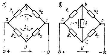
Rice. 1. Bridge circuits for connecting a resistor
An example of using a bridge circuit to connect resistors
The bridge circuit is also used to turn on the slide relay on some electric locomotives. The relay serves as a wheel slip detection sensor. Relay P (Fig. 2) is included in the diagonal of the bridge formed by two series-connected electric motors M1 and M2, through which the current Id flows (the electric motors in this case are considered sources with EMF E1 and E2), and two resistors with resistance R.
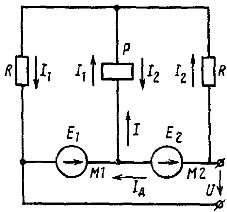
Rice. 2. Circuit diagram of the drive relay
In the absence of leakage, E1 = E2, therefore, the currents through the resistors, I1 = I2. Therefore, the current in the relay coil is I = I1 — I2 = 0.
When drifting, the rotational speed of the traction motor connected to the box wheel system increases sharply. At the same time, its e sharply increases. etc. with, for example, E1, and current I1. As a result, a current I = I1 — I2 will begin to flow through the coil of relay P, which will make it work. Relay P, with its auxiliary contact, turns on the alarm and sand feed or acts on the electric locomotive control system.