Measurement of parameters of semiconductor diodes and transistors
 Knowing the parameters of diodes and transistors makes it possible to improve the quality and reliability of the operation of electronic circuits based on diodes and transistors and to locate the place of malfunction during repair and adjustment of electronic equipment.
The main metrological characteristics of semiconductor device parameter testers are given on the front panels of the devices and in their passports.
Semiconductor diode and transistor parameter testers are classified according to the following criteria:
-
by type of indication — analog and digital,
-
by appointment — multimeters, measuring devices (testers) of parameters of semiconductor diodes, transistors and integrated circuits (L2), logic analyzers (LA).
The main metrological characteristics of the testers are: the purpose of the device, the list of measured parameters, the measurement range of the parameters, the measurement error of each parameter.
The suitability of semiconductor diodes, transistors and analog integrated circuits is checked by measuring qualitative parameters with their subsequent comparison with reference ones. If the measured parameters correspond to the reference ones, then the tested diode, transistor or analog integrated circuit is considered suitable.
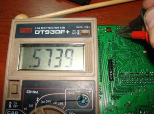
Multimeters (analog and digital) are used to check the integrity of p-n junctions in diodes and transistors. This operation is called «Dialing».
Checking the health of the diodes consists of measuring the forward and reverse resistance of the p-n junction. The ohmmeter is first connected with the negative probe to the anode of the diode and the positive probe to the cathode. With this on, the p-n junction of the diode is reverse biased and the ohmmeter will show a high resistance expressed in megohms.
Then the polarity of the bond is reversed. The ohmmeter registers a low forward p-n junction resistance. Low resistance indicates that in both directions the p-n junction of the diode is broken. A very high resistance indicates an open circuit in a p-n junction.
When "dialing" a p-n-junction with a digital multimeter, a special sub-range is introduced into it, indicated by the conventional graphic designation of the semiconductor diode on the parameter measurement limit switch. The operating voltage of the probes in this mode corresponds to 0.2 V, and the current passing through the probes does not exceed 1 μA. It is impossible to break through even the smallest semiconductor with such a current.
When checking bipolar transistors, you must remember that they have two p-n junctions and "ringing" in the same way as diodes. One probe is connected to the base terminal, the second probe alternately touches the collector and emitter terminals.
When "ringing" transistors, it is very convenient to use one function of a digital multimeter — when measuring resistance, the maximum voltage of its probes does not exceed 0.2 V. Since the p-n- junctions of silicon semiconductors open at a voltage above 0 .6 V, then in the resistance measurement mode with a digital multimeter, the p-n junctions of semiconductor devices soldered to the board do not open. In this mode, a digital multimeter, unlike an analog one, measures only the resistance of the device under test. In an analog multimeter, the probe voltage in this mode is sufficient to open p-n-junctions.
Some types of multimeters allow you to measure a number of qualitative parameters of bipolar transistors:
h21b (h21e) — current transfer coefficient in a circuit with a common base (common emitter),
Azsvo — reverse collector current (minority carrier current, thermal current),
h22 — output conductivity.
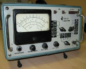
Specialized testers from the L2 group are more effective in checking the quality parameters of diodes and transistors.
The main parameters checked by the testers are different for diodes and transistors:
• for rectifier diodes — forward voltage UKpr and reverse current AzCobra,
• for zener diodes — stabilization voltage Uz,
• for bipolar transistors — transmission coefficient z21, reverse current collector Aznegov, output conductivity hz2, limit frequency egr.
Measurement of the main quality parameters of diodes.
In order to measure the quality parameters of the diodes with the tester L2, it is necessary to perform the following operations:
-
switch the «Diode / Transistor» switch to the «Diode» position,
-
switch the «Mode» switch to the «30» position,
-
set the «> 0 <» button on the front panel to the «I»Yes» position,
-
key "Mode / measure.»Set to» Meas. » and with the potentiometer «> 0 <» on the back panel of the tester, set the indicator arrow close to the zero mark,
-
"Mode / measure" key. set to middle position,
-
connect the tested diode to the contacts «+» and «-»,
Provide a diode reverse current measurement mode for which perform the following operations:
-
"Mode / measure" key. set to the «Mode» position, using the «Mode» switch (ranges 30, 100 and 400 V) and the «URV» knob, set the required value of the diode reverse voltage on the device indicator,
-
return the key «Mode / Measurement.» to the initial position and on the «10 U, I» scale of the device indicator, read the value of the reverse current by selecting such a measurement range using the upper right switch (0.1 — 1 — 10 — 100 mA) so it is possible to make a reliable reading of the indicator readings.
Measure the forward voltage of the diode, for which perform the following operations:
-
move the lower right switch to the «UR, V» position,
-
turn the upper right switch to position «3 ~»,
-
"Mode / measure" key. set to the «Mode» position using the «Mode» switch (ranges 30 and 100 mA) and «Azn mA «set the required value of the direct current according to the device indicator,
-
"Mode / measure" key. set to "Meas". and read the value of URpr after selecting such a measurement range (1 … 3 V) with the upper right switch so that the indicator readings can be counted. Return the "Mode / Measurement" key. to middle position.
Measurement of the main quality parameters of transistors.
Prepare the tester for work, for which perform the following operations:
-
set the «Diode / Transistor» switch to the «p-n-p» or «n-p-n» position (depending on the structure of the tested transistor),
-
connect the tested transistor to the holder according to the markings and the location of its terminals, the emitter of the tested transistor to the contact E2, the collector to the terminal «C», the base to «B»,
-
set the lower right switch to position «K3, h22»,
-
set the upper right switch to «▼ h» position,
-
"Mode / measure" key. set to "Meas". and using the "▼ h" knob, move the indicator arrow to the "4" division of the "h22" scale,
-
"Mode / measure" key. set to "Meas". and read the value of the output conductivity «h22» in μS on the scale of the indicator of the device. Return the "Mode / Measurement" key. to middle position.
Measure the current transfer coefficient of the transistor, for which perform the following operations:
-
set the lower right switch to position «h21»,
-
"Mode / measure" key. set to "Meas". and use the «t / g» key to move the indicator arrow to the «0.9» division of the «h21v» scale. Return the «Mode / Measurement» key. to middle position,
-
set the upper right switch to position «h21»,
-
"Mode / measure" key. set to "Meas". and on the "h21b" or "h21e" scale of the device's indicator, read the "h21" value. Return the "Mode / Measurement" key. to middle position.
Measure the minority carrier flow by performing the following operations:
• set the lower right switch to the position «Azsvo, ma «,
• Mode / Measure key. set to "Meas".and on the scale "10 U, Az»The device indicator reads the value of the return current of the collector Azsvo, by selecting the switch of the measurement range (0.1-1-10-100 mA) such a range, so that you can confidently reading of evidence. Return the "Mode / Measurement" key. to the «Measurement» position.