Electric circuits with capacitors
 Electric circuits with capacitors include sources of electrical energy and individual capacitors. A capacitor is a system of two conductors of any shape separated by a dielectric layer. Connecting the clamps of the capacitor to a source of electrical energy with a constant voltage U is accompanied by the accumulation of + Q on one of its plates, and -Q on the other.
The magnitude of these charges is directly proportional to the voltage U and is determined by the formula
Q = C ∙ U,
where C is the capacitance of the capacitor measured in farads (F).
The value of the capacitor's capacity is equal to the ratio of the charge on one of its plates to the voltage between them, i.e. C = Q / U,
The capacity of the capacitor depends on the shape of the plates, their dimensions, mutual arrangement, as well as the dielectric constant of the medium between the plates.
The capacitance of a flat capacitor, expressed in microfarads, is determined by the formula
C = ((ε0 ∙ εr ∙ S) / d) ∙ 106,
where ε0 is the absolute dielectric constant of the vacuum, εr is the relative dielectric constant of the medium between the plates, S is the area of the plate, m2, d is the distance between the plates, m.
The absolute dielectric constant of the vacuum is constant ε0 = 8.855 ∙ 10-12 F⁄m.
The magnitude of the electric field strength E between the plates of a flat capacitor under voltage U is determined by the formula E = U / d.
In the International System of Units (SI), the unit of electric field strength is the volt per meter (V⁄m).
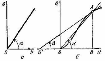
Rice. 1. Characteristics of pendant -volt of the capacitor: a — linear, b — non-linear
If the relative permeability of the medium located between the plates of the capacitor does not depend on the magnitude of the electric field, then the capacitance of the capacitor does not depend on the magnitude of the voltage at its terminals and the Coulomb-volt characteristic Q = F (U) is linear (Fig. 1 , a).
Capacitors with a ferroelectric dielectric, in which the relative permeability depends on the strength of the electric field, have a nonlinear characteristic of the Coulomb voltage (Fig. 1, b).
In such non-linear capacitors or varicons, each point of the coulomb characteristic, for example point A, corresponds to a static capacitance Cst = Q / U = (mQ ∙ BA) / (mU ∙ OB) = mC ∙ tan α and the differential capacitance Cdiff = dQ / dU = (mQ ∙ BA) / (mU ∙ O'B) = mC ∙ tanβ, where mC is a coefficient depending on the scales mQ and mU taken for charges and voltages, respectively.
Each capacitor is characterized not only by the value of the capacity, but also by the value of the operating voltage Urab, which is taken so that the resulting electric field strength is less than the dielectric strength.The dielectric strength is determined by the lowest value of the voltage at which the breakdown of the dielectric begins, accompanied by its destruction and loss of insulating properties.
Dielectrics are characterized not only by their electrical strength, but also by a very large bulk resistance ρV, ranging from about 1010 to 1020 Ω • cm, while for metals it is from 10-6 to 10-4 Ω • see
In addition, for dielectrics, the concept of specific surface resistance ρS is introduced, which characterizes their resistance to surface leakage current. For some dielectrics, this value is insignificant, and therefore they do not break through, but are blocked by an electric discharge on the surface.
In order to calculate the magnitude of the voltages at the terminals of individual capacitors included in multi-chain electrical circuits, at a given EMF sources of using electrical equations similar equations of Kirchhoff's laws for direct current circuits.
So, for each node of a multi-chain electric circuit with capacitors, the law of conservation of the quantity of electricity ∑Q = Q0 is justified, which establishes that the algebraic sum of charges on the plates of the capacitors connected to one node is equal to the algebraic sum of the charges, which were before they were connected to each other. The same equation in the absence of preliminary charges on the plates of the capacitor has the form ∑Q = 0.
For any circuit of an electric circuit with capacitors, the equality ∑E = ∑Q / C is true, which states that the algebraic sum of the emf in the circuit is equal to the algebraic sum of the voltages at the terminals of the capacitors included in this circuit.
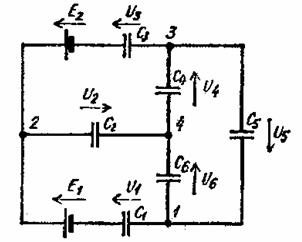
Rice. 2.Multi-circuit electric circuit with capacitors
So, in a multi-circuit electrical circuit with two sources of electrical energy and six capacitors with initial zero charges and arbitrarily selected positive directions of voltages U1, U2, U3, U4, U5, U6 (Fig. 2) based on the law of conservation of the amount of electricity for three independent nodes 1, 2, 3 we get three equations: Q1 + Q6-Q5 = 0, -Q1-Q2-Q3 = 0, Q3-Q4 + Q5 = 0.
The additional equations to three independent circuits 1—2—4—1, 2—3—4—2, 1—4—3—1, when surrounding them clockwise, have the form E1 = Q1 / C1 + Q2 / C2 -Q6 / C6, -E2 = -Q3 / C3 -Q4 / C4 -Q2 / C2, 0 = Q6 / C6 + Q4 / C4 + Q5 / C5.
The solution of a system of six linear equations allows you to determine the amount of charge on each capacitor Qi and find the voltage at its terminals Ui by the formula Ui = Qi / Ci.
The true directions of the stresses Ui, the values of which are obtained with a minus sign, are opposite to those originally assumed in the formulation of the equations.
When calculating a multi-chain electric circuit with capacitors, it is sometimes useful to replace capacitors C12, C23, C31 connected in a delta with capacitors C1, C2, C3 connected in an equivalent three-pointed star.
In this case, the required powers are found as follows: C1 = C12 + C31 + (C12 ∙ C31) / C23, C2 = C23 + C12 + (C23 ∙ C12) / C31, C3 = C31 + C23 + (C31 ∙ C23 ) / C12.
In the reverse transformation, use the formulas: C12 = (C1 ∙ C2) / (C1 + C2 + C3), C23 = (C2 ∙ C3) / (C1 + C2 + C3), C31 = (C3 ∙ C1) / ( C1 + C2 + C3).
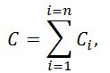
Capacitors C1, C2, …, Cn connected in parallel can be replaced by a single capacitor
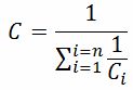
and when they are connected in series — a capacitor whose capacity is
If the capacitors included in the circuit have dielectrics with appreciable electrical conductivities, then small currents appear in such a circuit, the values of which are determined by the usual methods adopted when calculating direct current circuits, and the voltage at the terminals of each capacitor in steady state is found by the formula
Ui = Ri ∙ Ii,
where Ri is the electrical resistance of the dielectric layer of the ith capacitor, Ii is the current of the same capacitor.
See on this topic: Charging and discharging the capacitor