Drying of transformers
 Under operating conditions, the most economical and convenient methods of drying transformers have become widespread - induction and zero sequence. Drying can be done at any ambient temperature, but with the oil drained from the tank.
For induction drying (Fig. 1), the coil (2) is wound with an insulated wire on the transformer tank (1). In order to achieve a more even distribution of temperature inside the tank, the magnetizing coil is wound 40-60% of the height of the tank (from the bottom), and the turns are located more densely at the bottom than at the top.
The winding calculation is done as follows.
Number of turns ω = UA / l, where U is the supply voltage, V, l — perimeter of the tank, m, A — coefficient depending on the specific losses, m / V.
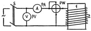
Rice. 1. Transformer drying scheme with tank losses
The value of coefficient A for different specific power losses
ΔP А ΔP А 0.75 2.33 1.4 1.74 0.8 2.26 1.6 1.65 0.9 2.12 1.8 1.59 1.0 2.02 2.0 1 .54 1.1 1.92 2.5 1.42 1.2 1.84 3.0 1.34
The specific loss factor is determined by the formula
ΔP = kT(F / Jo) (θ-θo),
where кT is the heat transfer coefficient (for an insulated tank кt = 5, for non-insulated k = 12 kW / m2x ° С), F — area of the transformer tank, m2, Fо — area of the tank occupied by the winding, m2, θ — tank heating temperature (usually 105 ° C), θо — ambient temperature, ° С.
Using ΔP the current in the coil is determined
I = ΔPFO/ (Ucosφ)
For transformers with a ribbed tank cosφ = 0.3, and for transformers with smooth and tubular tanks cosφ = 0.5 — 0.7.
Knowing the current, the cross section of the wire is selected from the tables. The temperature of the transformer can be adjusted by changing the supplied voltage, by changing the number of winding turns, or by intermittent switching off.
When drying with zero-sequence currents, the magnetizing coil is one of the transformer windings connected according to the zero-sequence scheme.
The transformers most often used in operation have a twelfth group of winding connections. In this case, it is convenient to use a low-voltage coil that has a derivative zero point (Fig. 2).
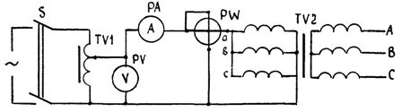
Rice. 2… Transformer drying circuit with zero-sequence currents
When the transformer is dried by zero sequence currents, the heating is due to the scattering of power in the magnetizing winding, in the steel of the magnetic circuit, in its structural parts and in the tank.
The drying parameters can be determined as follows. Power consumed by the magnetizing coil
Po = ΔPF,
where ΔР — specific energy consumption, kW / m2, F — tank area, m2.
For a transformer without thermal protection, the drying of which is performed at 100 - 110 ° C, you can take ΔR = 0.65 - 0.9 kW / m2.
The applied voltage when the magnetizing coil is star connected
Uo = √(POZo / 3cosφ),
Where ZO is an impedance of zero sequence of the coil phase (it can be determined empirically), cosφ = 0.2 - 0.7.
The phase current of drying the transformer needed to select measuring instruments and the cross -section of the power wires is determined by the expression
Io = Aznom√(10/Snom),
where Snom — rated power of the transformer.
Drying the transformer with zero sequence currents is characterized by significantly less power consumption and drying time (up to 40%) compared to the induction method. The disadvantage of this method is the need to have non -standard voltage power. Most often, a welding transformer is used for this purpose.