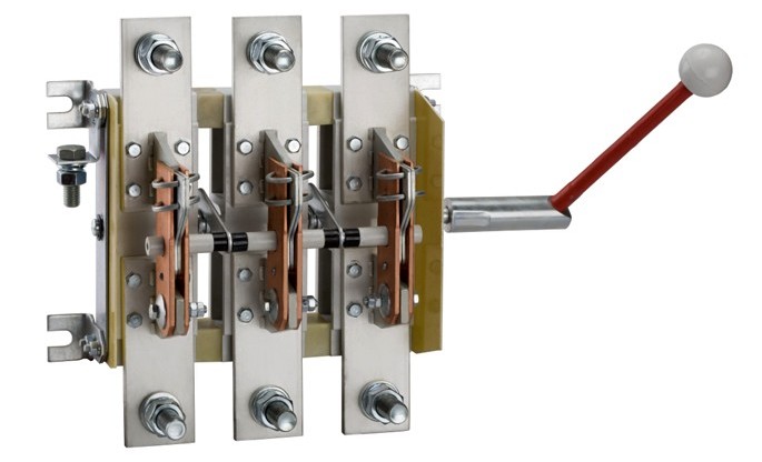
Switches - purpose, types, device, principle of operation
Knife switches are the simplest manual control devices that are used in alternating current circuits at voltages up to 660 V and direct current at voltages up to 440 V.
Knife switches and switches for currents from 100 to 1000 A are used in the switchgear of electrical installations and are used for non-automatic closing and opening of electrical circuits.
In addition to switches, manual switching devices include packages switches and switches, universal keys, controllers. These devices are used to turn on and off and switches are used to switch AC and DC electrical circuits at rated load.
Load capacity
All switches and switches allow continuous operation at an ambient temperature not higher than 40
OS and charge their rated AC or DC current.
Classification
Keys and knife switches are classified according to the following criteria:
1) by the value of the nominal current — 100; 200; 400; 600; 1000 A;
2) by the number of poles - single-pole, two-pole, three-pole:
3) from the presence of breaking contacts — with broken contacts, without breaking contacts.
Regardless of the presence of breaking contacts, the same circuit breakers and switches are suitable for direct and alternating current operation. But due to the worse conditions for extinguishing the arc of direct current, knife switches and switches without breaking contacts in direct current networks are used only as disconnectors;
4) by control method — with direct control for installation on the front side of the switchgear, with remote control for installation on the rear side of the switchgear;
5) by the method of connecting the wires — with the front connection of the wires, with the rear connection of the wires.
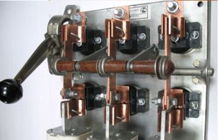
According to the number of poles, circuit breakers are divided into one-, two-pole and three-pole, according to the type of control current they are from the central and side handle, according to the connection method - from the front and back of the device.
Keys and knife switches are manufactured in single, double and three-pole versions with central or lever actuation for front or rear wiring. Switches with a central handle serve as a disconnector, that is, they disconnect previously disconnected electrical circuits, and with side handle and lever drives, they disconnect circuits under load.
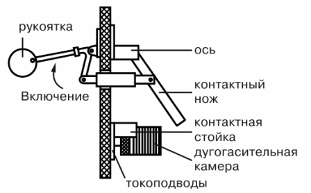
The principle of operation of the circuit breaker
A switch (switch) is a manually operated electrical device designed to switch electrical circuits.
Currently, the most common knife switches and tap-type switches for currents of 100 A and more are performed according to the principle of linear contact of a movable contact (knife) with a fixed contact rail. The linear contact provides low contact resistance, breaking large currents and reliability in operation.
In fig. 1 shows the principle of linear contact. The fixed contact pole 1 is in line with the movable contact knife 2, consisting of two strips with cylindrical protrusions 3, which provide contact with the pole along the line. The ends of the knife strips are covered with a flat spring 4.
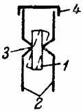
Rice. 1. Line contact
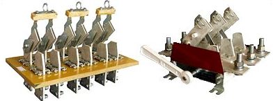
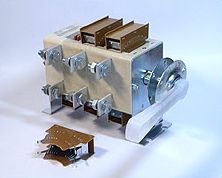
A general view of a bipolar switch is shown in fig. 2.
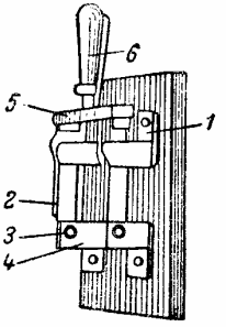
Rice. 2. Double pole switch
Each pole of the circuit breaker consists of a contact rail 1 with two jaws, between which there is a contact blade 2, rotating on an axis 3, fixed in the lower jaws 4. The contact blades are firmly connected to an insulating crosshead 5, on which an insulated handle is fixed 6.
Processes that occur when the circuit breaker opens
Opening the circuit with a switch causes a change in current, forming an electric field between the fixed and moving contacts. The strength of this field is proportional to the line voltage and inversely proportional to the distance between the contacts.
At the first moment when the switch is turned off, when the distance between the contacts is small, the electric field strength can reach a value of the order of several thousand or even tens of thousands of volts per centimeter, which naturally causes ionization of an air gap.
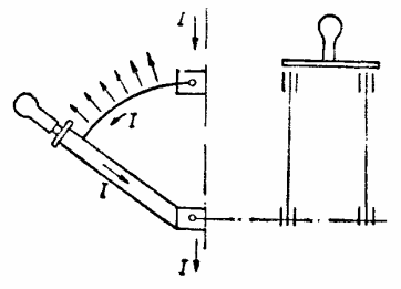
Rice. 3. Forces acting on the arc when the circuit breaker is tripped
With a sufficient degree of ionization, air gap breakdown will occur and an electric arc is formed… With direct current, the time of the arc than with alternating current, so it will exist for a longer time, as in the latter case, when the current passes through a zero value in each half-cycle, the arc is extinguished in a very short period of time.
Furthermore, it was found that the arc extinguished more rapidly the higher the interrupting current and the shorter the breaker blades. Physically, this is explained by the fact that at large currents that must be switched off, the forces of interaction between the current flowing in the current-carrying parts of the switch and the magnetic field of the arc accelerate its movement in the air and deionization.
The arc will experience the greater tensile force, the shorter the knife blades, because in this case the strength of the magnetic field acting on the arc increases.
When currents of 75 A or less are switched off, the forces acting on the arc are negligible and therefore the fastest possible arc extension is paramount. These currents (75 A and less) are interrupted by switches (switches) for 100 — 400 A, therefore the latter, in addition to the main knives, also have a break (torque knives) that provide sufficient speed to turn off the switch , regardless of the speed of the operator's hand, and protection of the main contacts from the destructive action of the arc.
Torque knives are made of a lightweight design, as they are charged for a short time - only during the shutdown process. Knife switches and switches for currents 600 A and above are manufactured without torque knives.
Deciphering knife switch designations
Letter designations of circuit breakers: P — switch; P — switch; the second letter — P — front connection of wires; B — with a side handle; Ts — with central connection. The numbers indicate: the first (1, 2 and 3) is the number of poles, the second is the rated current (1 — 100 A, 2 — 250 A, 4 — 400 A and 6 — 600 A).
Knife and side handle and lever operated wrenches are manufactured with and without arc chutes. Center handle knife wrenches are manufactured without arc chambers with spark arrestor contacts. The tightness of the contact surfaces of the knife and the jaws is ensured due to the spring properties of the material of the jaws (for switches up to 100 A) and due to the steel springs (for switches above 200 A).
To protect the blades from arc melting during tripping, high-current circuit breakers with spark-extinguishing or arcing contacts are used. The spark-extinguishing contacts with which the knives are equipped, when turned off, move away from the jaws under the action of their springs, regardless of the speed of the handle and the actuation of the switch.
The arcing contacts of the circuit breakers are located outdoors or inside the arcing chambers. They serve to ensure rapid extinguishment of the electric arc and to prevent its transfer to adjacent conductive or grounded distribution structures. Key switches have the same design as switches and are used to switch electrical circuits.
In some designs, circuit breakers are combined with fuses or fuses are used as knives. Such a design, which allows the performance of switching and protection functions, is called a fuse (FBB).
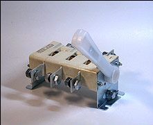
For the safety of the operating personnel, the switches are enclosed in a metal protective housing
Circuit breakers-disconnectors BP
Circuit breakers (knife switches) VR32-31, VR32-35, VR32-37, VR32-39 are designed for switching on, switching and disconnecting alternating current with a nominal voltage of up to 660 V, a nominal frequency of 50 and 60 Hz and a direct current with a nominal voltage up to 440V in electrical power distribution devices.
BP-32 one-way three-pole switch with side handle
BP-32 Side Handle Two-Way Three-Pole Circuit Breaker
Classification of BP switch-disconnectors:
According to the degree of protection of the handle: IP00, IP32.
By the presence of auxiliary contacts: without auxiliary contacts; with auxiliary contacts.
By the type of handle manual drive: without handle; side handle; front offset handle; side offset handle.
According to the location of the connection plane of the external clamps of the contact wires: 1 — parallel to the installation plane; 2 — perpendicular to the mounting plane; 3 — combined: input parallel, output perpendicular to the mounting plane; 4 — combined: input perpendicular, output parallel to the mounting plane.
By number of poles and number of directions: one-pole switch-disconnector, one road sign; double-pole switch-disconnector for one direction; three-pole unidirectional switch-disconnector; single-pole switch-disconnector for two directions; double-pole switch-disconnector for two directions; three-pole switch-disconnector for two directions.
Main technical characteristics of VR-32 circuit breakers:
rated operating voltage for the main circuit:
alternating current:
380, 660V.
direct current:
220, 440V
conventional free air heat current (Jth)
100, 250, 400 and 630 A
conventional thermal sheath current (Jth)
80, 200, 315 and 500 A.
AC rated frequency
50 and 60 Hz
Mechanical durability
for currents 100 and 250 A:
25000 cycles «VO»
for currents 400 and 630 A:
16000 cycles «IN»
Power consumed by the device per pole
BP32-31
3 watts
BP32-35
15 watts
BP32-37
35 watts
BP32-39
60 watts
Fuse blocks - circuit breaker
In order to reduce the overall dimensions of the switchgear, fuse blocks (BPV) are produced, which provide disconnection of rated currents and protection of circuits from current overloads and short circuits. In BVP, when the handle is turned, the traverse with the fuse placed on it moves and the contacts of the device open.
The presence of two interruptions per pole ensures the disconnection of rated currents up to 350 A with alternating U up to 550 V. To disconnect a rated direct current of 350 A at U up to 440 V, the interruptions are fed with arc networks.
Extraction of a cartridge with a burnt insert is possible only in the off position of the BPV after releasing a special latch. Electrical durability of the device 2500, mechanical 500 cycles.
Installation information
On-load switches must be installed in a vertical position. Busbars and wires must be connected to the fixed contacts of the switch, that is, so that when the switch is turned off, its moving blades are not energized.
Busbars and wires connected to circuit breakers must have a cross-section corresponding to the rated current of the circuit breaker and be reinforced so that mechanical loads from them are not transmitted to the terminals.Busbars and wires must be firmly tightened in the terminals of the circuit breakers to ensure reliable contact and prevent overheating of the latter.
When connecting the busbars and wires, the contact nuts of the switches and blade switches should be tightened smoothly without pulling out. In this case, after the first tightening, the nut should be loosened and then smoothly tightened again until failure.
Nuts must be screwed without jamming; it is recommended to lubricate their threads with technical petroleum jelly.
The surface of the contact blades of the blade switches should be lubricated with a small layer of castor oil to avoid them sticking in the contact racks. When cleaning, the thickened grease from the knife switches and switches is removed with clean gasoline.
The metal non-conductive parts of lever operated switches mounted on the front side of the shield must be earthed.