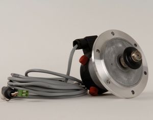
Speed sensors
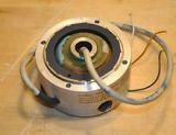 Tachogenerators—low-power DC and AC electrical machines—are used as rotational speed sensors in automation systems. Tachometer bridges are used to convert the rotation speed of electric motors into voltage.
DC tachogenerators
DC tachogenerators, depending on the method of excitation, are of two types: magnetoelectric (excited by permanent magnets) and electromagnetic (excited by a special coil) (Fig. 1 a, b).
Output voltage of the tachogenerator at constant excitation current Uout = E — IRi = hereω — IRI am
where Ce = (UI am — II amRI am)/ω — a machine constant determined by the passport data.
At idle (I= 0) voltage Uout = E = Ceω... Therefore, the static characteristic of the tachogenerator Uout = e (ω) at idle is linear, since Ce = const (straight line I, Fig. 1, c).
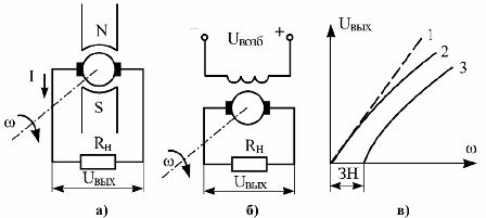
Rice. 1. Rotary sensors (DC tachometric generators): a) with permanent magnet excitation, b) with electromagnetic excitation, c) static characteristic
Under load, the static characteristic becomes non-linear (curve 2).its slope changes, which is a consequence of the armature reaction and the voltage drop in the armature winding of the tachogenerator. In real tachogenerators, there is a voltage drop on the brushes, which leads to the appearance of youth insensitive (curve 3).
To reduce the distortion of the static characteristics of tachogenerators, they are used at low loads (Azn = 0.01 — 0.02 A). Armature circuit current Azi = E / (Ri + Rn) and output voltage Uout = E — IRi = hereω — IRI am.
DC tachogenerators are widely used in automatic control systems for electric drives such as speed sensors. Their advantages are low inertia, high accuracy, small size and weight, and for magnetoelectric tachogenerators there is also no power source. The disadvantage is the presence of a collector with brushes.
AC tachogenerators
Synchronous tachogenerators are a single-phase synchronous machine with a rotor in the form of a permanent magnet (Fig. 2, a). In synchronous tachogenerators with a change in angular velocity, the frequency of the output voltage also changes with the amplitude. Static characteristics are non-linear. Dynamically synchronous tachogenerators are non-inertial elements.
An asynchronous tachogenerator is a two-phase asynchronous machine with a hollow non-magnetic rotor (Fig. 2, b). On the stator of the asynchronous tachogenerator there are two windings offset by 90 (excitation of the OF and the exhaust gas generator). The OB coil is connected to an AC source.
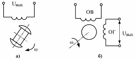
Rice. 2. Alternating current tachometer generators: a — synchronous, b — asynchronous
An EMF is induced in the exhaust coil, which is the output, when the rotor rotates. transformation and rotation.Under the influence of an electromotive force, the output of the tachogenerator rotates and there is a voltage Uout.
The static characteristic of an asynchronous tachogenerator is also non-linear. When changing the rotation of the rotor, the phase of the output voltage changes by 180 °.
Asynchronous tachogenerators are used as sensors for angular velocity, rotational velocity and acceleration. In the second case, the excitation coil of the asynchronous tachogenerator is connected to a direct current source.
The advantages of asynchronous tachogenerators are reliability, low inertia. Disadvantages — the presence of residual EMF at the output. with stationary rotor, relatively large dimensions.
Tachometric bridges
DC and AC tachometer bridges are used in automation systems to provide feedback on the rotational speed of electric motors. This makes it possible to simplify the system, since there is no need for an additional electrical machine - a tachogenerator. This reduces the static and dynamic load on the executive motor.
The DC tachometric bridge is a special bridge circuit (Fig. 3, a), in one of the arms of which the armature of the engine Ri is included, and in others - resistors R1, R2, Rp. A mains voltage U is applied to the diagonal ab of the bridge, which supplies the armature of the motor, and the voltage is removed from the diagonal cd Uout of proportion to the angular velocity ω.
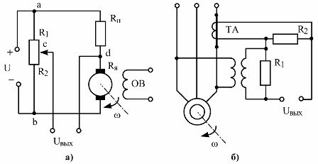
Rice. 3. DC tachometer bridge (a) and non-contact measuring device for the speed of rotation of an asynchronous motor (b)
If there is no current in the output circuit, then
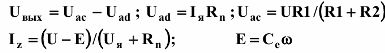
Solving the joint system of equations, we get

Tachometer bridge output voltage

where Ktm is the transmission coefficient of the tachometer bridge.
The error of the tachometer bridge is ± (2 — 5)%. Dynamic DC tachometer bridges are non-inertial coupling.
To control the speed of the rotor of an asynchronous electric motor, a non-contact measuring device (Fig. 3, b) is used, containing a measuring transformer of current TA and a TV with voltage.