Wiring diagrams of a voltage transformer
 In electrical installations, it is necessary to measure voltages between phases (line) and phase voltages with respect to earth (phase). Depending on this, single-phase, three-phase or groups of single-phase transformers are used, connected according to the corresponding schemes, which ensure the necessary measurements and the operation of the protections.
In fig. 1 shows the most common voltage transformer switching schemes.
In the diagram of fig. 1, but one is used single phase transformer… The circuit allows you to measure only one of the line voltages.
In fig. 1b shows two single-phase transformers connected according to the incomplete delta scheme. The circuit makes it possible to measure the three line voltages.
In the diagram of fig. 1, c shows the connection of three single-phase transformers according to the star scheme with a derivative zero point and grounding of the neutral of the primary windings. The chain allows you to measure everything line and phase voltage and monitor isolation in isolated neutral systems.
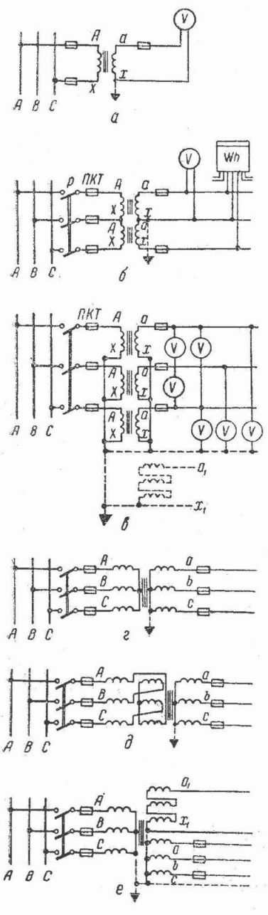
Rice. 1.Switching schemes of voltage transformers
In the diagram of fig. 1, d shows the inclusion of a three-phase three-level transformer, which allows you to change only line voltages. This transformer is not suitable for insulation monitoring and its primary must not be earthed.
The fact is that when the primary winding is grounded, in the event of a ground fault (in a system with an isolated neutral), large zero-sequence currents will appear in the three-tube transformer, and their magnetic flux, closing along the leakage paths (tank, structures, etc.) can heat the transformer to unacceptable temperatures.
The diagram (Fig. 1, e) shows the inclusion of a three-phase compensated transformer designed to measure only line voltages.
In the diagram of fig. 1, e shows the inclusion of a three-phase five-level NTMI transformer with two secondary windings. One of them is star-connected with a neutral point at the output and serves to measure all phase and line voltages, as well as to monitor insulation (in a system with an isolated neutral) using three voltmeters. In this case, the zero-sequence magnetic fluxes will not overheat the transformer, since they will be free to close through the two sidebands of the magnetic circuit.
Another winding is superimposed on the three main bars of the core and is connected in an open delta. Earth fault signaling relays and devices are connected to this coil.
Normally at the ends of the additional secondary winding the voltage is zero, when one of the network phases is closed to ground, the voltage rises to 3Uf it will be equal to the geometric sum of the voltages of the two undamaged phases. The number of turns of the additional winding is calculated so that in this case the voltage is equal to 100 V.
The overvoltage relay included in the open delta circuit will trip and provide an audible alarm.
Then, with the help of three voltmeters, it is determined in which phase the short circuit occurred. The grounded phase voltmeter will show zero and the other two lines will show voltage.
In a system with an isolated neutral on the busbars of all voltages, set voltmeters for insulation monitoring.