Schemes for inclusion of electric machine amplifiers
 Any independently excited electric generator can be called an electric machine amplifier (EMU), taking the excitation as input and the main circuit as output. The same can be said for the synchronous generator. In practice, an emu is usually referred to as a DC generator of special construction; it consumes extremely low power for its excitation compared to the rated power of this generator.
The most widespread in the electric drive is the transverse field amplifier. The design feature of such an amplifier is that two pairs of brushes AA and BB are located on the collector in mutually perpendicular planes, in the longitudinal and transverse axes (with bipolar construction). In this case, the brushes AA in the transverse axis are short-circuited, and the brushes BB in the longitudinal axis belong to the main current circuit of the generator (Fig. 1).
The amplifier has several field coils called control coils and one compensation coil.. One of the control coils is independently powered by a DC source.It is called main and consumes low power compared to the power of the ECU main current terminals. This coil is normally powered by a stabilized DC source. The remaining control coils are designed to adjust the set value and stabilize the operation of the amplifiers of electric machines.
Read more about the device and how EMU works in this article: Electromechanical amplifiers
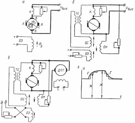
Rice. 1. Circuits for switching on EMU and flexible feedback with brushes
In fig. 1, b shows a schematic diagram of an ECU with two additional voltage feedback coils for the ECU output. The operating system coil is called a stabilizer and is a flexible feedback loop for the ECU output voltage. It can be turned on by a capacitor, but most often by a transformer called a stabilizing transformer.
The current in this coil, and therefore the flux, can only occur when the voltage across the EMU terminals changes (increases or decreases). In principle, flexible feedback only responds to changes in the controlled parameter. Mathematically speaking, we can say that in the general case, flexible feedback responds to the first or second time derivative of the controlled parameter (eg current voltage, etc.).
The OH coil is connected directly to the ECU voltage, therefore current flows through it at all times of operation. The current and therefore the flux in this coil is proportional to the voltage. With this connection, the OH coil serves as a hard voltage feedback.
In fig. 1, in the EMU it is used as a generator powering the engine, and in fig. 1, d shows a plot of voltage as a function of time, which explains what has been said about feedbacks.
Let's consider the operation of the feedback coils in the example of using the EMU as an exciter to the generator of the conversion block of the G-D system (Fig. 2).
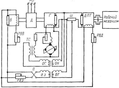
Rice. 2. Scheme for inclusion of an electric machine amplifier as an exciter generator in the G system-e
Here, a conventional generator-motor (G-D) feeds a DCT motor with direct current. In this case, the excitation coil of the generator G is powered not by the exciter B, but by the ECU, the main coil of which is fed through the rheostat PB3 and the switch P from the exciter B of the conversion unit.
In addition to this coil, the EMU is equipped with three coils: OS, OH and OT.
OS — stabilizing feedback coil. It is connected in parallel to the main circuit of the ECU through a stabilizing transformer TS and ensures stable operation of the IUU. During normal operation, the voltage value in the main circuit of the ECU is unchanged and therefore the current does not pass through the stabilization coil of the OS.
When the voltage changes across the secondary winding of the TS transformer, e is induced. d. s proportional to the change in ECU voltage. This e. etc. v. creates a current in the circuit of the control coil and therefore a magnetic flux Phos. As the voltage increases, the flux from the OS winding is directed to the flow of the main OZ coil, and as the voltage decreases, the flux from the OS winding has the same direction as the main flux and thus restores voltage to the ECU terminals.
OH — voltage feedback coil. It is connected to the voltage U of the main circuit of the generator. The flux of the OH winding is directed to the flux of the main winding.
As the voltage of the main circuit of the generator increases, the flux from the OH winding increases, and due to the opposite direction of the EMU fluxes, the total magnetic flux decreases, and the voltage tends to take the same value. As the voltage U decreases, the resulting flux increases, preventing the voltage from decreasing. At constant load (I= const) and constant voltage value, the motor speed is kept constant.
OT is a solid current feedback coil connected through a shunt Ш in the main current circuit of the generator. As the load increases, that is, as the current in the main circuit increases, the voltage at the motor terminals decreases due to an increase in the voltage drop in the main current circuit.
To maintain a constant engine speed, it is necessary to compensate for this voltage drop, i.e. to increase the generator voltage. For this, the flux of the OT winding must have the same direction as the flux of the main winding.
As the load decreases, the motor speed should increase at a constant voltage U. However, this will reduce the flux in the OT winding and, accordingly, the total excitation flux. As a result, the voltage will decrease by such an amount that the motor will strive to maintain a given ° Speed.
The same coil can be used to maintain a constant current in the main circuit. In this case, it would be necessary to change the polarity in the OT winding so that the flow is in the opposite direction.