Waveform and voltage measurement
 The shape of the voltage and current curves is considered practical sinusoidal, if any of its ordinates differs from the corresponding ordinate of a sinusoid equal to it in amplitude, with a segment not exceeding 5% of the amplitude.
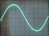
Sinusoidality can be tested in several ways. Using the simplest of them, observe the investigated curve on the screen of a cathode-ray oscilloscope.
For this, two identical sinusoidal lines are previously drawn on the screen of the device or on a transparent plate, shifted vertically relative to each other by 10% of their amplitude (Fig. 1).
The voltage under test is then applied to the Y input of the oscilloscope, and by adjusting the gain on the Y channel and the sweep period, size the screen curve so that it lies within the band limited by the auxiliary sinusoids. If this succeeds, then the voltage is considered to be practically sinusoidal.
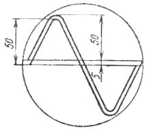
Rice. 1. Auxiliary curves for determining current and voltage shape using a cathode ray oscilloscope
To consider the second way of determining the sinusoidality of a curve, we introduce several definitions. As you know, the value of a periodic variable can be characterized by the effective, average and maximum (amplitude) values. If the periodic quantity x changes according to a sinusoidal law, then all its values are related to each other in a certain way.
For example, the ratio of the amplitude value to the effective value, called the crest coefficient ka = xm/ x = √2 = 1.41, the ratio of the average value for half a period to the amplitude value, called the average value coefficient kCp = xcp / xm = 2 /π = 0.637 and finally the ratio of the effective value to the average value, called the aspect ratio ke = x / xCp = π / (2√2) = 1.11.
Focusing on these ratios, the standard allows to determine the sinusoidal shape of the curve of a periodic quantity based on the results of the simultaneous measurement of the average and effective values. The curve is considered nearly sinusoidal if 1.132> kph> 1.088.
Due to the fact that most of the measuring instruments used in practice are calibrated in average values, it is not always possible to directly measure the mean and median values. In this case, the investigated value is measured simultaneously by amplitude (peak) and electrodynamic voltmeters. If it is necessary to determine all three named coefficients, a rectifier voltmeter should be connected.
The readings of the voltmeter and the coefficients characterizing the sinusoidality of the form are related to the following ratios: ka = 1.41U1/ U2, кf = U2/0.9U3, kcp = 0.673 = U3/ U1, where U1, U2, U3 — readings of amplitude, electrodynamic and rectifier scale voltmeters calibrated in mean sinusoidal voltage values.
An example. To determine the non-sinusoidal shape of the voltage curve of the secondary winding of the transformer, the phase voltage is measured simultaneously with amplitude V3-43, electrodynamic D-556 and rectifier Ts4317 voltmeters.
Their readings were U1 = 76 V, U2 = 61 V, U3 = 59.5 V. Then ka = 1.41 x 76/61 = 1.76, ke = 1.11 x 61 / 59.5 = 1, 14, kcp = 0.637 x 59.5 / 76 = 0.5
Due to the fact that for a sinusoidal curve, these coefficients should be 1.41, 1.11 and 0.637, respectively, it can be concluded that the voltage of the secondary winding of the transformer has a non-sinusoidal form. Pay attention to the fact that with a sinusoidal voltage, the readings of all three voltmeters should be equal.