Repair of cable lines
Monitoring of the technical condition of cable lines
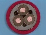 The operation of cable lines has its own characteristics, since it is not always possible to detect defects in it by simple inspection. Therefore, checks of the insulation condition, load and temperature monitoring of the cable are carried out.
From the point of view of insulation tests, cables are the most difficult element of electrical equipment. This is due to the possible long length of the cable lines, heterogeneity of the soil along the length of the line, inhomogeneity of the cable insulation.
To identify gross defects in cable lines produce measuring insulation resistance with a megohmmeter for a voltage of 2500 V. However, the readings of the megohmmeter cannot serve as a basis for the final assessment of the insulation condition, since they are highly dependent on the length of the cable and the defects in the connection.
This is due to the fact that the capacity of the power cable is large, and during the resistance measurement it does not have time to fully charge, therefore the readings of the megohmmeter will be determined not only by the steady-state leakage current, but also by the charging current and the measured value of the insulation resistance will be significantly underestimated.
The main method of monitoring the condition of the insulation of a cable line is high voltage test… The purpose of the tests is to identify and promptly remove developing defects in the insulation of cables, connectors and terminals to prevent damage during operation. At the same time, cables with a voltage of up to 1 kV are not tested with increased voltage, but the insulation resistance is measured with a megohmmeter with a voltage of 2500 V for 1 min. It should be at least 0.5 MOhm.
Inspection of short cable lines within a switchgear is carried out no more than once a year, as they are less susceptible to mechanical damage and their condition is monitored more often by personnel. The overvoltage test of cable lines above 1 kV is carried out at least once every 3 years.
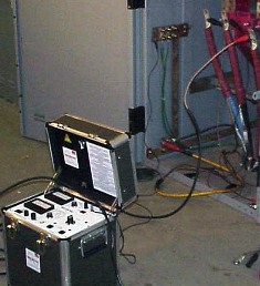
The main method of testing the insulation of the cable lines is to test with an increased DC voltage... This is because the AC installation has a much higher power under the same conditions.
The test setup includes: transformer, rectifier, voltage regulator, kilovoltmeter, microammeter.
When checking insulation, voltage from a megohmmeter or test rig is applied to one of the cable cores while its other cores are securely connected to each other and grounded.The voltage is raised smoothly to the specified value and maintained for the required time.
The condition of the cable is determined by the leakage current... When it is in a satisfactory condition, the increase in voltage is accompanied by a sharp increase in the leakage current due to the charging of the capacitance, after which it decreases to 10 - 20% of the maximum value. The cable line is considered suitable for operation if, during the tests, there was no destruction or overlap on the surface of the termination, no sudden current surges and a noticeable increase in the leakage current.
Systematic overloading of cables lead to deterioration of insulation and reduction of line duration. Insufficient loading is associated with insufficient use of the conductive material. Therefore, during the operation of the cable line, it is periodically checked whether the current load in them corresponds to that established when the object was put into operation. The maximum permissible loads of the cables are determined by the requirements PUE.
The load on the cable lines is monitored at the time determined by the chief energy engineer of the enterprise, but at least 2 times a year. In this case, after the specified control is carried out during the period of the autumn-winter maximum load. Control is carried out by monitoring the readings of the ammeters of the power substations, and in their absence, using portable devices or clamp meter.
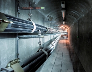
Permissible current loads for long-term normal operation of cable lines are determined using tables given in electrical manuals.These loads depend on the method of laying the cable and the type of cooling medium (earth, air).
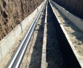
For cables laid in the ground, the long-term permissible load is taken from the calculation for laying one cable in a trench at a depth of 0.7 — 1 m at a ground temperature of 15 ° C. For cables laid outdoors, it is assumed that the ambient temperature environment is 25 ° C. If the calculated ambient temperature differs from the accepted conditions, then a correction factor is introduced.
The highest average monthly temperature of all months of the year at the cable depth is taken as the calculated ground temperature.
The calculated air temperature is the highest average daily temperature that is repeated at least three times a year.
The long-term permissible load of the cable line is determined by the sections of the lines with the worst cooling conditions, if the length of this section is at least 10 m. Cable lines up to 10 kV with a preload factor of no more than 0.6 — 0 ,8 can be overloaded in a short time. Permissible overload levels, taking into account their duration, are given in the technical literature.
To more accurately determine the load capacity, as well as when the operating temperature conditions change, control the temperature of the cable line... It is impossible to directly control the core temperature on a working cable, since the cores are under tension. Therefore, the temperature of the sheath (armor) of the cable and the load current are measured at the same time, and then the core temperature and the maximum permissible current load are determined by recalculation.
Measuring the temperature of the metal sheaths of a cable laid outdoors is done with conventional thermometers that are attached to the armor or lead sheath of the cable. If the cable is buried, the measurement is done with thermocouples. It is recommended to install at least two sensors. The wires from the thermocouples are laid in the pipe and brought out to a convenient and safe place from mechanical damage.
The temperature of the wire must not exceed:
-
for cables with paper insulation up to 1 kV — 80 ° C, up to 10 kV — 60 ° C;
-
for cables with rubber insulation — 65 ° C;
-
for cables in polyvinyl chloride sheath — 65 ° C.
In the event that the current-carrying conductors of the cable heat up above the permissible temperature, measures are taken to eliminate overheating - they reduce the load, improve ventilation, replace the cable with a cable with a larger cross-section and increase the distance between the cables.
When cable lines are laid in soil that is aggressive to their metal sheaths (salt marshes, swamps, construction waste), soil corrosion from lead shells and metal sheaths... In such cases, periodically check the corrosive activity of the soil, water sampling and soil. If at the same time it is found that the degree of corrosion of the soil threatens the integrity of the cable, then appropriate measures are taken — removal of contamination, replacement of the soil, etc.
Determining the locations of cable line damage
Determining the locations of damage to cable lines is quite a difficult task and requires the use of special equipment. The work of repairing damage on the cable line begins with establishing the type of damage... In many cases, this can be done with the help of a megohmmeter.For this purpose, from both ends of the cable, the condition of the insulation of each wire relative to the ground, the integrity of the insulation between the individual phases and the absence of breaks in the wire are checked.
Determining the location of the failure is usually done in two stages — first, the failure zone is determined with an accuracy of 10 — 40 m, and then the location of the defect on the track is specified.
When determining the area of damage, the causes of its occurrence and the consequences of the damage are taken into account. The most commonly observed breaking of one or more conductors with or without grounding, it is also possible to weld sheathed conductors with a long-lasting short-circuit current flow to ground. During preventive tests, a short circuit of a live wire to ground, as well as a floating breakdown, most often occur.
Several methods are used to determine the damage zone: pulse, oscillatory discharge, loop, capacitive.
The pulse method is used for single-phase and phase-to-phase faults, as well as for wire breaks. The oscillating discharge method is resorted to with a floating breakdown (occurs at high voltage, disappears at low voltage). The feedback method is used with single-, two- and three-phase faults and the presence of at least one intact core. The capacitive method is used to break the wire. In practice, the first two methods are the most widespread.
When using the pulse method, relatively simple devices are used. To determine the area of damage from them, short pulses of alternating current are sent to the cable. Arriving at the place of damage, they are reflected and sent back.The nature of the cable damage is judged by the image on the device screen. The distance to the fault location can be determined by knowing the travel time of the pulse and the speed of its propagation.
Using the pulse method requires reducing the contact resistance at the point of failure to tens or even fractions of an ohm. For this purpose, the insulation is burned by converting the electrical energy delivered to the location of the fault into heat. Combustion is carried out with direct or alternating current from special installations.
Oscillating discharge method consists in charging the damaged cable core from the rectifier to the breakdown voltage. At the moment of failure, an oscillatory process occurs in the cable. The period of oscillation of this discharge corresponds to the time of the double movement of the wave to the location of the fault and back.
The duration of the flickering discharge is measured with an oscilloscope or electronic milliseconds. The measurement error by this method is 5%.
Find out the location of the cable fault directly along the route using the acoustic or induction method.
An acoustic method based on the fixation of the vibrations of the ground above the location of the cable line failure caused by a spark discharge at the location of the insulation failure. The method is used for faults such as «floating fault» and broken wires. In this case, the damage is determined in the cable located at a depth of 3 m and under water up to 6 m.
A pulse generator is usually a high voltage DC setup from which pulses are sent to the cable. Ground vibrations are monitored with a special device.The disadvantage of this method is the need to use mobile DC installations.
Induction method finding the places of cable damage is based on fixing the nature of the changes in the electromagnetic field above the cable, through the conductors of which a high-frequency current passes. The operator, moving along the track and using an antenna, amplifier and headphones, determines the location of the fault. The accuracy of determining the location of the fault is quite high and amounts to 0.5 m. The same method can be used to establish the route of the cable line and the depth of the cables.
Cable repair
Repair of cable lines is carried out according to the results of inspections and tests. A feature of the work is the fact that the cables to be repaired can be energized, and in addition, they can be located near live cables that are under voltage. Therefore, personal safety must be observed, do not damage nearby cables.
Repair of cable lines can be associated with excavation. To avoid damage to nearby cables and utilities at a depth of more than 0.4 m, excavation is carried out only with a shovel. If cables or underground communications are found, the work is stopped and the person responsible for the work is notified. After opening, care must be taken not to damage the cable and connectors. For this purpose, a massive board is placed under it.
The main types of work in case of damage to the cable line are: repair of armored coating, repair of housings, connectors and end fittings.
In the presence of local breaks in the armor, its edges at the place of the defect are cut off, soldered with a lead sheath and covered with an anti-corrosion coating (bitumen-based varnish).
When repairing a lead sheath, the possibility of moisture penetration into the cable is taken into account. To check, the damaged area is immersed in paraffin heated to 150 ° C. In the presence of moisture, the immersion will be accompanied by cracking and release of yen. If moisture is found, then the damaged area is cut out and two connectors are installed, otherwise the lead sheath is restored by applying cut lead pipe to the damaged area and then sealing it.
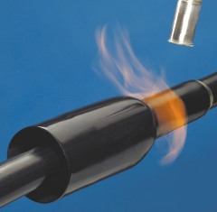
For cables up to 1 kV, cast iron connectors were previously used. They are bulky, expensive and not reliable enough. On 6 and 10 kV cable lines, mainly epoxy and lead connectors are used. Currently, modern heat-shrinkable connectors are actively used in the repair of cable lines... There is a well-developed technology for installing cable seals. The work is performed by qualified personnel who have received appropriate training.
Terminals are classified as indoor and outdoor applications. Dry cutting is often done indoors, more reliable and convenient to use. The external end connectors are made in the form of a funnel made of roofing iron and filled with mastic. When carrying out current repairs, the condition of the final funnel is checked, there is no leakage of the filling mixture and it is refilled.