Electric meters in pictures
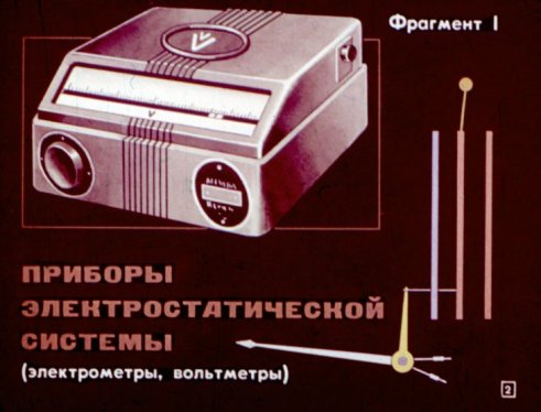
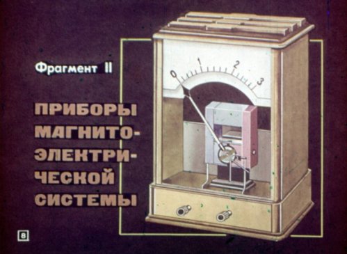
The pictures shown below are taken from the physics educational film «Electrical measuring devices». The filmstrip consists of five sections: devices of the electrostatic system (electrometers, voltmeters), devices of the magnetoelectric system, devices of the electromagnetic system, ohmmeters and devices of the electrodynamic system (wattmeters).
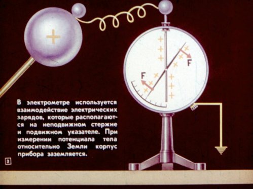
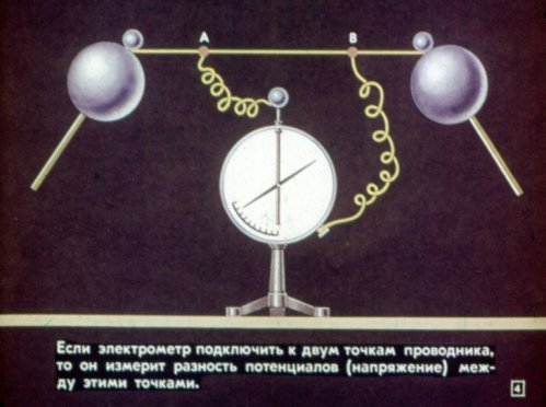
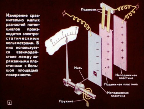
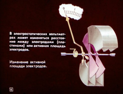
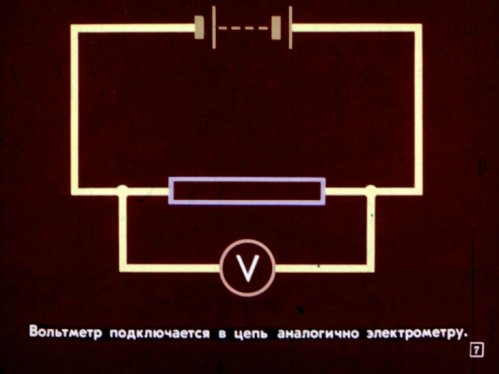
The measurement of relatively small potential differences is done with electrostatic voltmeters. They use the interaction between charged plates with a large surface area. In electrostatic voltmeters, the distance between the electrodes (plates) or the active area of the electrodes can be changed. Very clearly and in detail about static electricity in pictures is described here: Static electricity in a school filmstrip
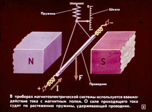
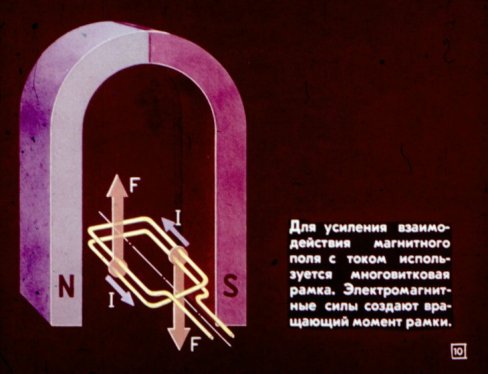
In the devices of the magnetoelectric system, the interaction of the current with a magnetic field is used. The strength of the passing current is estimated by the tension of the spring that holds the wire.
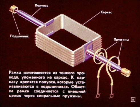
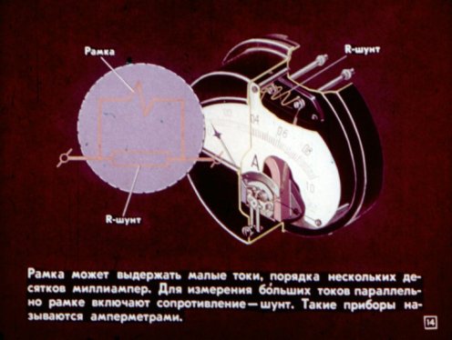
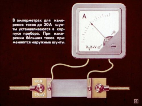
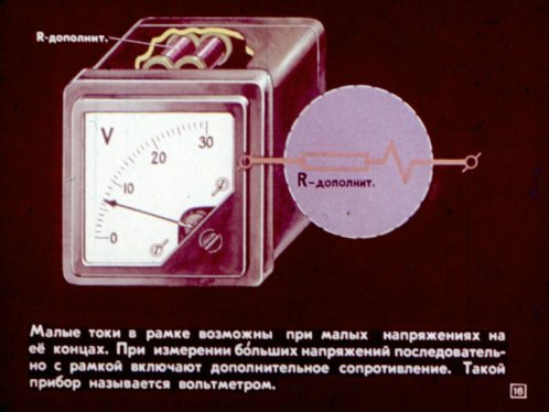
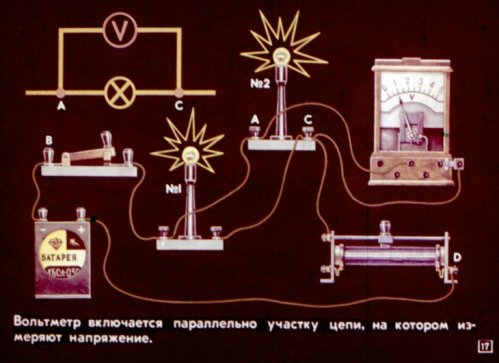
To improve the interaction of the magnetic field with the current, a multi-turn frame is used. Electromagnetic forces create the frame torque. The frame withstands small currents, on the order of several tens of milliamperes. To measure large currents, a shunt resistance is included in parallel with the frame. Such devices are called ammeters. In ammeters for measuring currents up to 30 A, shunts are installed in the housing of the device. When measuring large currents, external shunts are used. Small currents in the frame are possible with low voltage at its ends. When measuring high voltage, an additional resistance is included in series with the frame. Such a measuring device is called a voltmeter. The voltmeter is connected in parallel with the section of the circuit where the voltage is measured.
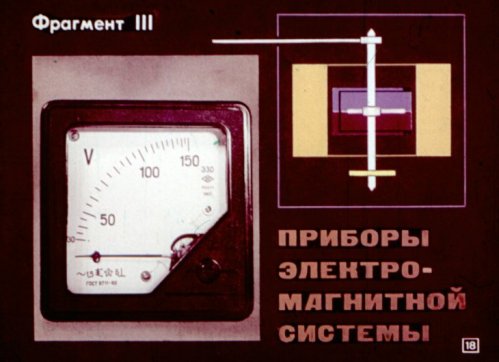
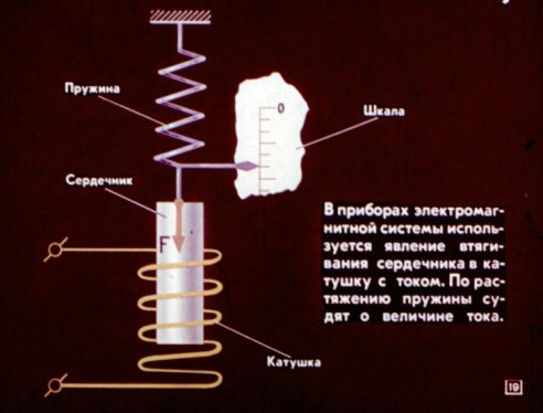
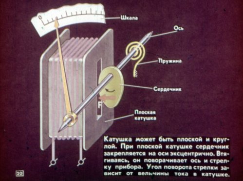
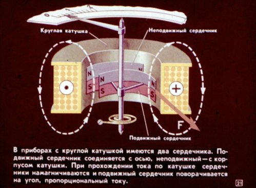
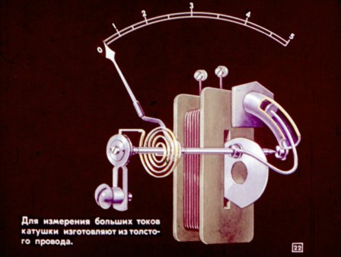
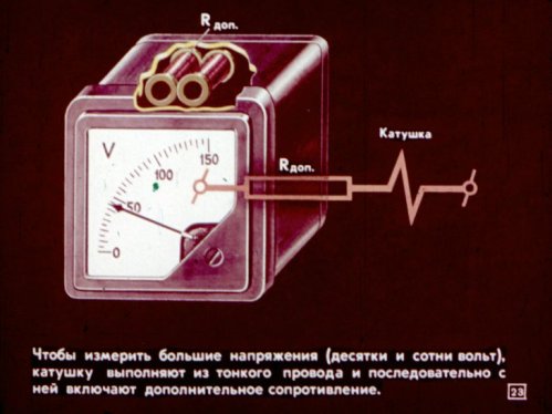
In measuring instruments of the electromagnetic system, the phenomenon of core retraction in the current coil is used. The amount of current is estimated by the tension of the spring. The coil can be flat or round. To measure large currents, the coils are made of thick wire. To measure high voltage (tens and hundreds of volts), the coil is made of a thin wire and an additional resistance is connected in series with it.
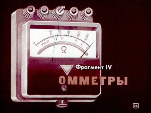
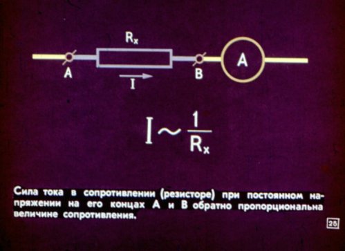
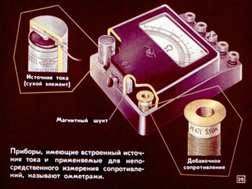
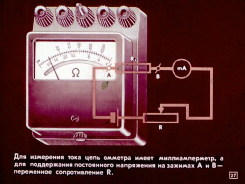
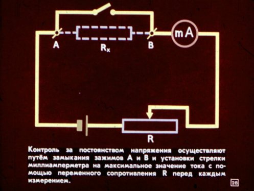
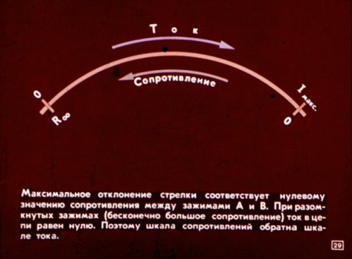
Measuring devices that have a built-in current source and are used to directly measure resistances are called ohmmeters. To measure the current, the ohmmeter circuit has a milliammeter, and to maintain a constant voltage across the terminals, a variable resistance.The constancy of the voltage is monitored by closing the clamps and adjusting the needle of the milliammeter to the maximum value of the current using a variable resistance before each measurement. The maximum deflection of the arrow corresponds to zero resistance between the clamps. When the clamps are open (infinite resistance), the current in the circuit is zero. Therefore, the resistance scale is the opposite of the current scale.
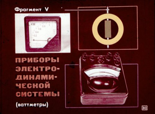
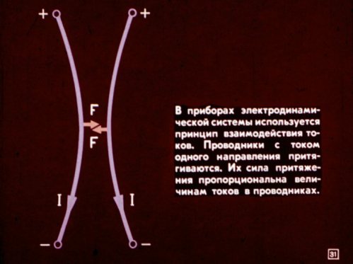
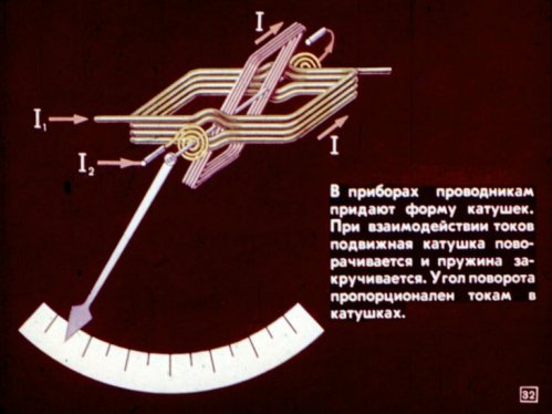
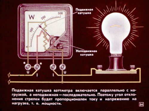
In the devices of the electrodynamic system, the principle of interaction of currents is used. Conductors with current in one direction are attracted. Their force of attraction is proportional to the magnitude of the currents in the wires. In the devices, the wires are formed into coils. When the currents interact, the moving coil rotates and the spring is twisted. The angle of rotation is proportional to the currents in the coils.
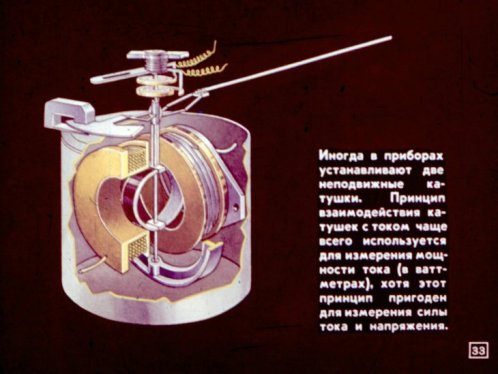
The moving coil of the wattmeter is connected in parallel with the load and the stationary coil is connected in series. Therefore, the turn-off angle of the arrow will be proportional to the current and voltage in the load, i.e. the power.
Other Electrical Engineering Educational Filmstrips:
The phenomenon of electromagnetic induction
Magnetic action of current
Electric stations