Characteristics and starting properties of synchronous motors
 The mechanical characteristic of the synchronous motor has the form of a horizontal straight line, that is, its rotation speed does not depend on the load (Fig. 1, a). As the load increases, the angle θ increases — the angle between the vectors of the network voltage Uc and the EMF of the stator winding E0 (Fig. 1, b).
From the vector diagram, you can derive the formula for the electromagnetic moment
M = (m1/ω1)(U1E0 / x1) sinθ,
where m1 — number of stator phases; ω1 — the angular velocity of the stator field; U1 — stator voltage; E0 — EMF induced in the stator winding; NS1 — inductive resistance of the stator winding; θ — the angle between the vectors of the magnetizing forces of the stator and the rotor. It follows from this formula that the moment changes depending on the load according to the sinusoidal law (Fig. 1, c).
No load angle θ = 0, i.e. voltage and emf are in phase. This means that the stator field and the rotor field coincide in direction, that is, the spatial angle between them is zero.
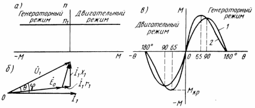
Rice. 1.Characteristics (a, b) and vector diagram (6) of a synchronous motor: I — stator current; r1 — active resistance of the stator winding; x1 — inductive resistance created by leakage current and armature current
As the load increases, the torque increases and reaches a critical maximum value at θ = 80 ° (curve 1), which the motor is able to create at a given grid voltage and field current.
Usually the nominal angle θnumber (25 ≈ 30) °, which is three times lower than the critical value, therefore the overload capacity of the motor is Mmax / Mnom = 1.5 + 3. The larger value applies to motors with implicit pronounced poles of the rotor, and the smaller one - with pronounced ones. In the second case, the characteristic (curve 2) has a critical moment at θ = 65 °, which is caused by the influence of the reactive torque.
In order not to synchronize the motor when overloading or reducing the mains voltage, it is possible to temporarily increase the excitation current, that is, to use forced mode.
With uniform rotation, the starting winding does not affect the operation of the motor. When the load changes, the angle θ changes, which is accompanied by an increase or decrease in speed. Then the starting winding begins to play the role of stabilizing. The asynchronous torque arising in it smooths out fluctuations in the speed of the rotor.
A synchronous motor is characterized by the following initial properties:
- Az* n = AzNS //Aznom — the multiple of the starting current flowing through the stator at the initial moment of starting;
- M * n = Mn / Mnom — the multiple of the starting torque, which depends on the number of rods of the starting coil and on their active resistance;
- M * in = MVh / Mnom — the set of input torque developed by the motor in asynchronous mode before it is pulled into synchronism at slip s = 0.05;
- M * max = Mmax / Mnoy — the set of the maximum torque in the synchronous mode of the motor;
- U* n = Un • 100 /U1 — the lowest permissible stator voltage at start-up,%.
Synchronous electric drive is used in installations that do not require frequent starting and speed control, for example for fans, pumps, compressors. A synchronous electric motor has a higher efficiency than an asynchronous one, it can work with overexcitation, i.e. with a negative angle φ, thus compensating inductive power other users.
Although a synchronous motor is more complex in design, requires a direct current source, and has slip rings, it is found to be more cost-effective than an induction motor, especially for driving powerful mechanisms.