Economical and effective solutions for the reconstruction of power supply facilities
 Currently, a huge number of outdated transformer substations operate in the country's power transmission networks. Basic statistics persistently inform us that 69.2% of the equipment [1], which according to all regulations and requirements has a service life of 12 years — cabinets based on electromechanical relay protection and automation devices, is operated for a long time beyond the established service life .
The operation of outdated equipment often leads not only to emergency situations filled with power outages, but also to a reduction in power and less electricity received.
In addition, in the conditions of existing electricity production, the main power engineers of the power supply of the facilities are faced with several tasks:
1. How to remove equipment from the power system with minimal equipment downtime?
2.How to reduce the significant costs of purchasing new equipment, construction and installation work on changing the construction part to fit the dimensions of the new substation?
There are two methods for solving these problems: the first method is the development and construction of new complete switchgear or the complete replacement of outdated electrical equipment and the introduction of new equipment according to individual projects using ready-made solutions and components, and the second method is the modernization of the existing substation equipment.
but global reconstruction of substations with complete replacement of outdated working equipment requires large financial investments. In the current conditions of the country and the reduction in the allocation of funding, the implementation of the tasks required by regulatory and regulatory instructions, the modernization of substations is significantly complicated.
Modernizing the switchgear, with the shortest possible downtime and using the existing concrete and steel structural elements as economically as possible, is what an economical energy manager can take on board.
The advantages of this modernization method are obvious:
-
there is no need to develop a project for the construction of new facilities;
-
no construction and assembly works are required;
-
such reconstruction is carried out in the shortest possible time, excluding a long-term lack of electricity;
-
losses from electricity production during reconstruction are minimized (disruption of the distribution system occurs one at a time);
-
warranty service is established for a period of 3-5 years for all installed equipment;
-
the reliability of the substation increases;
-
eliminates the need to write off and dispose of dismantled cells;
-
the cost of refurbishing the outdated substation is significantly saved.
An effective and economical option in this case is a partial modernization of the substation of equipment for relay protection and automation devices and 10 (6) kV distribution cabinets or modernization.
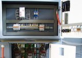
Rice. 1. KSO 393 on 6 (10kV)
The conversion includes:
-
revision of the secondary connection diagrams of relay cabinets, panels of relay protection and automation devices, drawings of pull-out trolley and revision of cells 6 (10kV);
-
dismantling of obsolete and defective components (switching devices for relay protection and automation, switches) of one or a certain number of equipment for devices for relay protection and automation, 10 (6) kV cells in the facility;
-
electrical installation and installation of new, easy-to-use, high-quality equipment for relay protection and automation devices based on static relays of our manufacture and a withdrawable block with a vacuum breaker of the facility;
-
commissioning and facility commissioning of the organization.
Consider upgrading a relay cabinet of a 6 (10) kV switchgear or KSO cell using the example of schematic diagrams of secondary connections (Figure 2)
Initially, 4 electromechanical current relays were used in the secondary switching circuits of the outgoing line switchgear. and a one-shot relay.
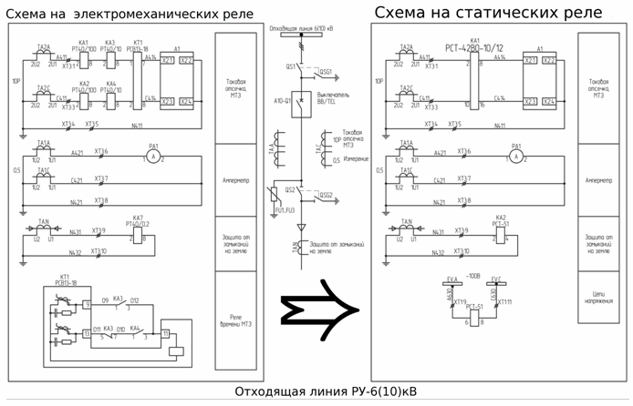
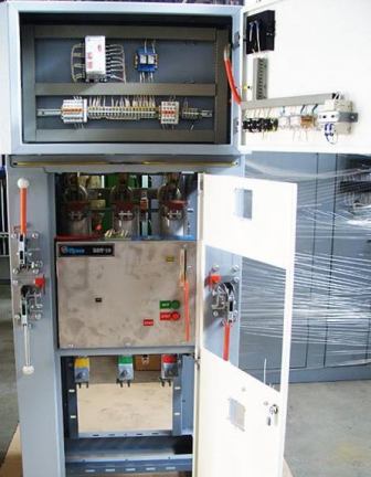
Photo 2
The result of the re-equipment of the secondary connecting circuits shows how a RST-42VO series static two-phase current relay makes it possible to realize the functions of maximum current protection and current interruption, which are actuated with an independent delay, by replacing 4 electromechanical current relays and a time relay that has exhausted its service life.
The advantages of this method:
-
reduced financial costs for replacing worn equipment,
-
reduced number of configuration and maintenance operations,
-
the PCT 42 VO relay does not require an additional power supply, since powered by input current,
-
interchangeable with old style electromechanical relays,
-
do not lose performance at low temperatures -40 C (tested during operation and time)
At the same time, the RST-42VO relay meets the requirements of TR CU 020/2011 «Electromagnetic compatibility of technical equipment» based on test report No. 239 / a dated June 29, 2014, issued by the Testing Center » AcademSib «in Novosibirsk .
In a similar way, the replacement of obsolete relay protection devices in IDM circuits is carried out.
Literature:
1. Appendix No. 1 to the minutes of the Board of Directors of JSC "Russian Networks" dated June 22, 2015 No. 356 pr. CONCEPT FOR THE DEVELOPMENT OF RELAY PROTECTION AND AUTOMATION OF THE ELECTRICAL COMPLEX.
Authors of the article: Osipov R.O. Shekhter M.A. LLC «Reon-Techno»