How to check the windings of transformers and chokes for short circuits
Device for checking the windings of transformers and chokes for the absence of a short circuit
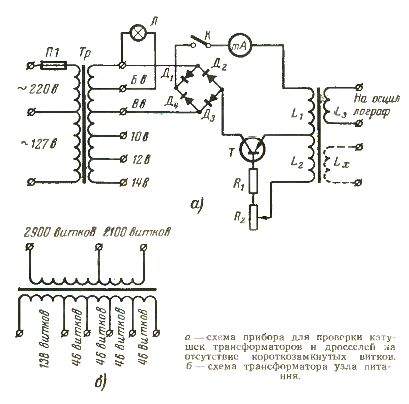
Inspection of transformers and suffocating the absence of winding breaks is usually done by a tester. But checking for the absence of a short circuit can be done in different ways, for example, using a device whose electrical circuit is shown in the figure.

This device is a low-frequency oscillator operating in a near-laser mode. The coil under test (in the diagram the coil Lx is shown with a dotted line) is placed on the core of the coils L1, L2 and L3 of the device.
In case the coil under test is in good condition and does not contain a single short circuit, the arrow on the device shows some current. If there is at least one short circuit in the coil, the generation of the device is interrupted and the needle of the device goes to zero or approaches zero.
You can make such a device in any electrical workshop.
Circuit element data: Diodes D1 — D4, type D7B, transistor type P14. Resistances: Rl type MLT -0.5 — 300 ohms, R2 type SP — 1 pc.
Coils L1, L2, L3 are wound on an ebonite or getinax frame. Windings L1 and L2 are wound in one of the frame sections, and winding L3 in the other. PEL wire 00.33 — 0.38 mm is used for all windings. The winding is done randomly.
Coil L1 contains 200 turns, L2 - 600 turns and L3 - 260 turns. A 140-length, 8-mm-diameter F-600 brand ferrite rod used in pocket and portable receiver antennas was used as the core.
Milliammeter with scale 0 — 50 ma.
The power supply unit of the device consists of a transformer (see figure b)... The windings of the transformer are made: primary from PEL wire 0.1 mm, secondary from PEL wires 0.41 mm. The core of the transformer is assembled from placTin 0.35 mm. Dial thickness 15 mm.
The secondary winding is made with taps, which are necessary to select the voltage supplied to the bridge of the rectifier.
