Wear of electrical contacts
During operation, the switching contacts are frequently switched on and off. This leads to wear and tear. Wear of the contacts is allowed so that it does not lead to a malfunction of the device until the end of the service life.
Contact wear is the destruction of the working surface of the contacts with a change in their shape, size, weight and reduction in immersion.
Wear of electrical contacts, which occurs under the influence of mechanical factors, is called mechanical wear... The contacts of disconnectors are exposed to mechanical wear — devices that open the electrical circuit without a load. Wear is manifested in the form of crushing and flattening of the end contacts and wear of the cut contact surfaces.
To reduce mechanical wear, movable or fixed contacts are provided with a spring that presses the contact to its stop in the off position of the device, eliminating the possibility of contact vibrations.In the on position, the contact, which has a spring, moves away from the stop, and the spring presses the contacts against each other, providing contact pressure.
The most intensive wear occurs under the influence of electrical factors, in the presence of a current load. This wear is called electrical wear or electrical erosion.
The most common measure of electrical contact wear is volumetric or weight loss of the contact material.
Contacts designed for switching electrical circuits under load are subject to mechanical and electrical wear. In addition, the contacts wear due to the formation of films on their surface of various chemical compounds from the material of the contacts with the environment, which is called chemical wear or corrosion.
When an electric circuit is commutated with an electric load, an electric discharge occurs on the contacts, which can turn into a powerful one electric arc.
Closing the wear process
When the contacts touch in the process of closing them, the spring contact is thrown back under the influence of elastic forces. There may be several contact rejections, i.e. contact vibration with damped amplitude is observed. The amplitude of the vibrations decreases with each subsequent impact. Rejection time is also reduced.
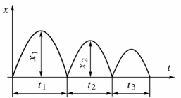
Vibration of the contacts when the device is turned on: x1, x2 — amplitude of rejections; t1, T2, T3 — waste of time
When the contacts are ejected, a short arc is formed, melting the contact points and vaporizing the metal. In this case, an increased pressure of metal vapors is created in the contact zone and the contact "hangs" in the flow of these vapors.The time to close the contact is increased.
The wear of the electrical contacts when switched on depends on the initial depression at the moment of contact of the contacts, the stiffness of the spring that creates the contact pressure, and on the physical properties of the contact materials.
Initial push of the contacts at the time of their contact — this is the force that counteracts the rejection of contacts when they collide. The greater this force, the smaller will be the amplitude and time of rejection, the smaller will be the vibration of the contacts and their wear. As spring stiffness increases, contact rejection decreases and contact wear decreases.
The higher the melting point of the contact material, the lower the contact wear. The higher the current in the switched circuit, the greater the wear on the contacts.
Open wear process
At the moment of opening the contacts, the contact pressure is reduced to zero. In this case, the contact resistance increases and the current density at the last point of contact increases. The contact point melts and an isthmus (bridge) of molten metal forms between the diverging contacts, which then breaks. A spark or arc may occur between the contacts.
Under the influence of high temperature during ejection, part of the metal of the contact isthmus is vaporized, part is ejected from the contact gap in the form of splashes, and part is transferred from one contact to another. Erosion phenomena are observed on the contacts — the appearance of craters on them or the sticking of metal.The wear of the contacts depends on the type and magnitude of the current, the duration of the arc burning and the material of the contacts.
With direct current, the transfer of material from one contact to another occurs more intensively than with alternating current, since the direction of the current in the circuit does not change.
At low currents, erosion of the contacts is caused by the destruction of the contact isthmus not in the middle, but closer to one of the electrodes. More often, the interruption of the contact isthmus is observed at the anode - the positive electrode.
A transfer of metal to the electrode further away from the melting point, usually the cathode, is observed. The transferred metal solidifies on the cathode in the form of sharp protrusions that worsen the contact conditions and reduce the gap between the contacts in the open state. The amount of erosion is proportional to the amount of electricity passed through the contacts during the spark discharge. The greater the current and the burning time of the arc, the greater the erosion of the contacts.
At high currents in industrial electrical networks, arcing often occurs between open contacts. Arc contact wear depends on many factors. Among them, the following factors can be avenged: mains voltage, type and magnitude of current, magnetic field strength, circuit inductance, physical properties of contact materials, cycle switching frequency, nature of contact contact, contact opening speed.
The electric arc between the contacts ignites at a certain voltage value.In the presence of arc extinguishing devices causing the movement of the arc, the arc will mix from the contacts when an inter-contact gap of 1 - 2 mm appears, which is not related to the magnitude of the voltage. Therefore, contact wear is practically independent of voltage. The minimum values of voltage at which an electric arc occurs for a number of metals used as contacts are given in a table. 1.
Table 1. Minimum arc voltage and current for selected metals
Circuit parameters Contact material Au Ag Cu Fe Al Mon W Ni Minimum current, A 0.38 0.4 0.43 0.45 0.50 0.75 1.1 1.5 Minimum voltage, V 15 12 13 14 14 17 15 14
Contact wear increases as the breaking current increases. This dependence is close to linear. At the same time, the change in current leads to a change in the external magnetic field, which affects the nature of contact wear. Contact wear is more intense at direct current, which is related to the delay in extinguishing the arc. With direct current, the contacts wear unevenly.
The movement of the arc in arc extinguishing devices occurs in a magnetic field created by a current-carrying wire. As the strength of the magnetic field increases, the speed of movement of the reference points of the arc increases. At the same time, the contacts heat up less and melt, and wear is reduced. However, when an isthmus of molten metal occurs between the open contacts, the increase in magnetic field strength increases the electrodynamic forces that tend to eject the molten metal from the contact gap.This leads to increased wear of the contacts.
Contact wear is affected by the inductance of the circuit as it is related to the time constant of the circuit and the rate of change of the current. In a constant current circuit, increasing inductance can reduce wear when the contacts are closed because the current rises more slowly and does not reach its maximum value when the contacts drop.
In an AC circuit, increasing inductance can increase and decrease short-circuit wear. It depends on when the contacts are discarded. When the contacts open, the inductance of the circuit affects the wear if it affects the current and the time to extinguish the arc.
More intensive wear is observed in contacts made of pure contact materials (copper, silver) and significantly decreases in contacts made of alloys with refractory components (copper — tungsten, silver — tungsten).
Silver has relatively high wear resistance at currents up to 63 A, at currents of 100 A and higher, the wear resistance decreases, and at currents of 10 kA it becomes one of the least wear-resistant materials.
Contact wear increases with increasing switching frequency. The more often the device is turned on, the more the contacts heat up and their resistance to erosion decreases. Increasing the contact opening speed will shorten the arcing time and reduce arc wear on the contacts.
The parameters of the electrical contacts (fault, solution, pressure) and the nature of the contact (point or planar contact, distorted contact) affect both mechanical wear and electrical wear.For example, as the contact solution increases, their wear increases, as the release of thermal energy in the arc cylinder increases.
Worn electrical contacts can lead to poor contact and loss of contact connections. This can cause premature failure of the switching device. Contact wear is affected by their rejection under the influence of electrodynamic forces.
Shterbakov E.F.