Induction voltage regulator — device, circuits, application
On the basis of an induction machine with a wound rotor, an induction regulator can be built, used for voltage regulation. The rotor of the machine must be equipped with a mechanical turning device.
The scheme of the induction regulator is shown in fig. 1. The rotor as well as the start terminals of the stator winding are connected to the network and the load is connected to the terminals of the end of the stator winding.
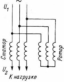
Rice. 1. Schematic of an induction voltage regulator
The rotor currents create a rotating magnetic field, which induces an additional EMF E2 in the stator windings, the value and phase of which depend on the angle of rotation of the rotor α... As a result, according to the vector diagram in fig. 2, when the number of turns in the windings is equal, the output voltage U2 can be adjusted from zero (at α = 180 °) to double the mains voltage (at α = 0).
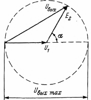
Rice. 2. Vector diagram of the induction regulator
The disadvantage of the considered simplest regulator is the change in the phase of the output voltage. Therefore, a double induction regulator is sometimes used, consisting anyway of two machines whose stator windings are connected in series.
The corresponding inclusion of the rotor windings (Fig. 3) ensures the rotation of their magnetic fields in opposite directions. Therefore, an EMF E2 is induced in the stator windings with a displacement in opposite directions from the zero position. After summing the EMF, we get the result, which is in phase with the supply voltage.
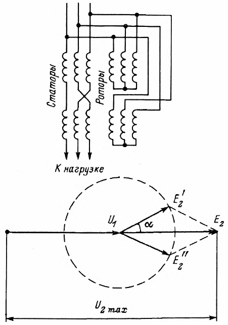
Rice. 3. Schematic and vector diagram of a dual controller
Induction regulators are very convenient for laboratory use. However, they are widely used in power systems where they are equipped with automatic voltage regulation devices.