Sliding Contact Rheostats — Principle of Operation and Diagram
A rheostat is a device that allows you to change the resistance of an electrical circuit and thus regulate the amount of current in it. According to their design, rheostats are divided into wired and wireless. In a wire rheostat, the conductive part is the wire, and in the non-conductive part, the conductive metal layer deposited on a base of insulating material.
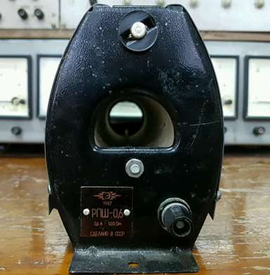
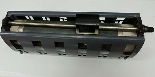
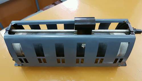
The most common wirewound rheostats are sliding contact. They make it possible to smoothly change the resistance of the electric circuit. In fig. 1 shows one of the types of sliding contact rheostats in practice.
A constantan wire or other alloy used to make a rheostat wire is wound over its ceramic tube. The coils of this wire are placed on the ceramic tube closely together, so that when the slider slides over them, they cannot be displaced. A metal guide rod is attached to the rheostat mounts along which the slide is moved.The latter, with the help of its clamping contacts, is tightly pressed to the turns of the rheostat wire and thus ensures reliable contact of the wire with the slider.
The rheostat has three clamps, two of which are mounted on the channels, one on each. The third clamp is attached to the guide rod of the rheostat.
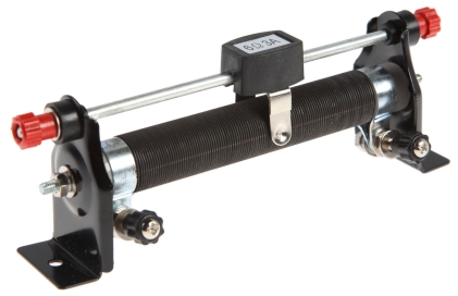
Rice. 1. Rheostat with sliding contact
In fig. 2 shows a circuit diagram of a rheostat with a movable contact for regulating the amount of current in the circuit.
The rheostat is connected to the circuit through terminals 1 and 2, the first of which is connected to the start of the rheostat coil, and the second to the slider. Clamp 3, connected to the end of the rheostat coil, remains free — not connected to the circuit. By moving the sliding contact of the slider along the turns of the rheostat wire, it is possible to smoothly change the value of the resistance of the rheostat introduced into the circuit.
Rice. 2. Switching on a rheostat with a sliding contact to regulate the current in the circuit
In the extreme left position of the sliding contact of the slider, that is, when it is mounted directly to clamp 1, the resistance of the rheostat introduced into the circuit becomes minimal — practically equal to zero. When the sliding contact of the slider is mounted to clamp 3, then the resistance of the rheostat introduced into the circuit becomes maximum.
For the device of rheostats, a rheostatic wire is used, made of various metal alloys, for example nickeline, constantan, nickel silver, etc., or of pure metals, for example, iron or nickel.
The rheostat conductor must have a high resistance, a low temperature coefficient and withstand stable continuous heating with current up to several hundred degrees Celsius.Materials such as nickel silver, nickeline and rheothan are cheap, easy to process, but do not allow heating to more than 200 ° C. As for constantan and other copper-nickel alloys, they can withstand prolonged heating up to 500 ° C.
Rheostats with sliding contacts are very diverse both in terms of construction and electrical data. As an example, we can indicate rheostats of the RP type (sliding rheostat): rheostat of the RP -3 type, designed for resistances of 500 — 1000 Ohm and, accordingly, for limiting currents of 0.6 — 0.4 A, rheostat of the RP -4 type — for resistances of 1000 — 2000 Ohms and, respectively, for currents of 0.4 — 0.2 A and RP-5 type rheostat (in a protected metal case) — for resistances of 18 — 200 Ohms and, respectively, for currents of 4 — 1 A.
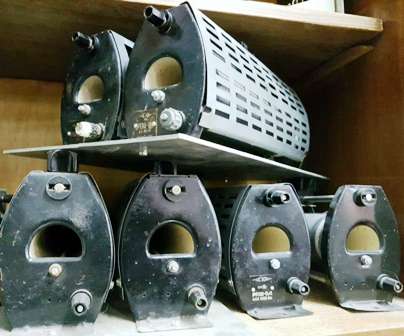
The figures below show the appearance of one of the types of sliding contact wound wire rheostats that are widely used in measurement and teaching laboratories.