Three-phase mains supply: active, reactive, full
The values of the total active and total reactive power of the three-phase circuit are equal to the sums of the active and reactive power for each of the three phases A, B and C, respectively. This statement is illustrated by the following formulas:
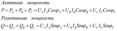
here Ua, Ub, Uc, Ia, Ib, Ic are the values of phase voltages and currents and φ is the phase shift.
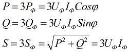
When the load is symmetrical, that is, in conditions where the active and reactive power of each of the phases are equal to each other, to find the total power of the multiphase circuit, it is enough to multiply the value of the phase power by the number of phases involved. The total power is determined based on the obtained values of its active and reactive components:
In the above formulas, the phase values of the quantities can be expressed in terms of their linear values, which will differ for star or delta connection schemes for users, but the power formulas will ultimately be the same:
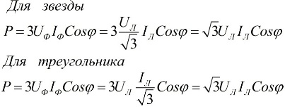
It follows from the above expressions that regardless of the connection scheme of the receivers of electrical energy, whether it is a triangle or a star, if the load is symmetrical, then the formulas for finding the power will have the same form, both for a triangle and for a star:
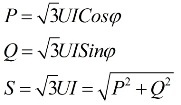
These formulas show linear values of voltage and current and are written without subscripts. Usually such a notation is found, without subscripts, that is, if there are no subscripts, then we mean linear values.
A special measuring device, called wattmeter… Its readings are determined by the formula:
in the above formula, Uw and Iw are the vectors of the voltage applied to the load and the current flowing through it.
The nature of the active load and the phase connection diagram can be different, therefore, depending on the specific circumstances, the connection diagrams of the wattmeter will be different.
For symmetrically loaded three-phase circuits, for a rough measurement of the total active power, if high accuracy is not required, one wattmeter connected to only one of the phases is sufficient. After that, to get the value of the active power of the entire circuit, it remains to multiply the readings of the wattmeter by the number of phases:
For a four-wire circuit with a neutral wire, to accurately measure active power, three wattmeters are required, each of which is read and then summed to obtain a value for the total power of the circuit:
If there is no neutral wire in a three-phase circuit, then two wattmeters are sufficient to measure the total power, even if the load is unbalanced.
In the absence of a neutral conductor, the phase currents are interconnected according to Kirchhoff's first law:
Then the sum of the readings of a pair of wattmeters will be equal to:
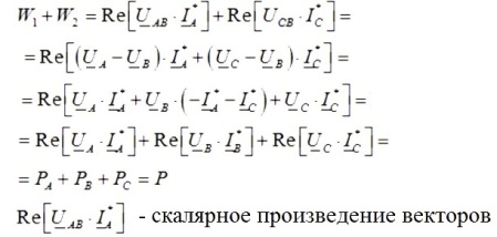
So, if you add the readings of a pair of wattmeters, you get the total active power in the three-phase circuit under study, and the readings of the wattmeters will depend on both the size of the load and its nature.
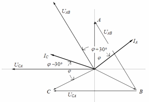
Looking at the vector diagram of currents and voltages in connection with a symmetrical load, it can be concluded that the readings of wattmeters are determined by the following formulas:
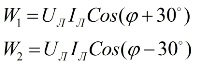
After analyzing these expressions, it can be understood that with a purely active load, when φ = 0, the readings of the two wattmeters will be equal to each other, that is, W1 = W2.
With active load inductance, when 0 ≤ φ ≤ 90 °, the readings of wattmeter 1 will be less than those of wattmeter 2, that is, W1 60 °, the readings of wattmeter 1 will be negative, that is, W1 <0.
With an active-capacitive nature of the load, when 0 ≥ φ≥ -90 °, the readings of the wattmeter 2 will be smaller than the wattmeter 1, that is, W1> W2. At φ <-60 °, the readings of the wattmeter 2 will become negative.