Modes of operation of synchronous generators, operating characteristics of generators
 The main quantities characterizing the synchronous generator are: terminal voltage U, charging I, apparent power P (kVa), rotor revolutions per minute n, power factor cos φ.
The most important characteristics of the synchronous generator are as follows:
-
idle characteristic,
-
external characteristic,
-
regulating characteristic.
No-load characteristic of a synchronous generator
The electromotive force of the generator is proportional to the magnitude of the magnetic flux Ф created by the excitation current iv and the number of revolutions n rotor of the generator per minute:
E = cnF,
where s — proportionality factor.
Although the magnitude of the electromotive force of a synchronous generator depends on the number of revolutions of the rotor, it is impossible to adjust it by changing the speed of rotation of the rotor, because the frequency of the electromotive force is related to the number of revolutions of the rotor of the generator, which must is kept constant.
Therefore, there remains the only way to adjust the magnitude of the electromotive force of a synchronous generator — this is a change in the main magnetic flux F. The latter is usually achieved by adjusting the excitation current iw using a rheostat introduced in the excitation circuit of the generator. In the event that the excitation coil is supplied with current from a direct current generator located on the same shaft with this synchronous generator, the excitation current of the synchronous generator is adjusted by changing the voltage at the terminals of the direct current generator.
Dependence of the electromotive force E of the synchronous generator on the excitation current iw at a constant nominal rotor speed (n = const) and a load equal to zero (1 = 0) is called the idling characteristic of the generator.
Figure 1 shows the no-load characteristic of the generator. Here, the ascending branch 1 of the curve is removed as the current iv increases from zero to ivm, and the descending branch 2 of the curve — when iv changes from ivm to iv = 0.
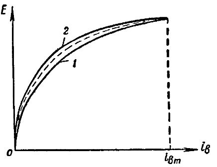
Rice. 1. Idle characteristic of a synchronous generator
The divergence between the ascending 1 and descending 2 branches is explained by residual magnetism. The larger the area bounded by these branches, the greater the energy losses in the steel of the magnetization reversal synchronous generator.
The steepness of the rise of the idle curve in its initial straight section characterizes the magnetic circuit of the synchronous generator. The lower the amp-turn flow rate in the generator air gaps, the steeper the generator idle characteristic will be, under other conditions.
External characteristics of the generator
The terminal voltage of a loaded synchronous generator depends on the electromotive force E of the generator, the voltage drop in the active resistance of its stator winding, the voltage drop due to the dissipation self-induction electromotive force Es and the voltage drop due to the armature reaction.
It is known that the dissipative electromotive force Es depends on the dissipative magnetic flux Fc, which does not penetrate the magnetic poles of the generator rotor and therefore does not change the degree of magnetization of the generator. The dissipative self-induction electromotive force Es of the generator is relatively small and therefore can be practically neglected. Accordingly, that part of the electromotive force of the generator that compensates for the dissipative self-induction electromotive force Es can be considered practically equal to zero.
The armature response has a more noticeable effect on the mode of operation of the synchronous generator and, in particular, on the voltage at its terminals. The degree of this influence depends not only on the size of the generator load, but also on the nature of the load.
Let us first consider the effect of the armature reaction of a synchronous generator for the case where the generator load is purely active. For this purpose we take part of the circuit of a working synchronous generator shown in fig. 2, a. Shown here is a portion of the stator with one active wire on the armature winding and a portion of the rotor with several of its magnetic poles.
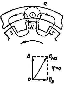
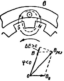
Rice. 2. Influence of the armature reaction under loads: a — active, b — inductive, c — capacitive nature
At the moment in question, the north pole of one of the electromagnets rotating counterclockwise with the rotor just passes under the active wire of the stator winding.
The electromotive force induced in this wire is directed towards us behind the plane of the drawing. And since the generator load is purely active, the armature winding current Iz is in phase with the electromotive force. Therefore, in the active conductor of the stator winding, the current flows towards us due to the plane of the drawing.
The magnetic field lines created by electromagnets are shown here in solid lines, and the magnetic field lines created by the armature winding wire current are shown here. - a dotted line.
Below in fig. 2, a shows a vector diagram of the magnetic induction of the resulting magnetic field located above the north pole of the electromagnet. Here we see that the magnetic induction V the main magnetic field created by the electromagnet has a radial direction, and the magnetic induction VI of the magnetic field of the armature winding current is directed to the right and perpendicular to the vector V.
The resulting magnetic induction The cut is directed up and to the right. This means that some distortion of the underlying magnetic field has occurred as a result of the addition of the magnetic fields. To the left of the North Pole it weakened somewhat, and to the right it increased a little.
It is easy to see that the radial component of the resulting magnetic induction vector, on which the magnitude of the induced electromotive force of the generator essentially depends, has not changed. Therefore, the armature reaction under a purely active load of the generator does not affect the magnitude of the electromotive force of the generator.This means that the voltage drop across the generator with a purely active load is due solely to the voltage drop across the active resistance of the generator if we neglect the leakage self-induction electromotive force.
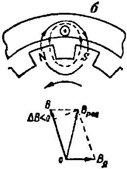
Let us now assume that the load on a synchronous generator is purely inductive. In this case, the current Az lags behind the electromotive force E by an angle of π / 2... This means that the maximum current appears in the conductor a little later than the maximum electromotive force. Therefore, when the current in the armature winding wire reaches its maximum value, the north pole N will no longer be under this wire, but will move a little further in the direction of rotation of the rotor, as shown in Fig. 2, b.
In this case, the magnetic lines (dotted lines) of the magnetic flux of the armature winding are closed through two adjacent opposite poles N and S and are directed to the magnetic lines of the main magnetic field of the generator created by the magnetic poles. This leads to the fact that the main magnetic path is not only distorted, but also becomes slightly weaker.
In fig. 2.6 shows a vector diagram of the magnetic inductions: the main magnetic field B, the magnetic field due to the armature reaction Vi and the resulting magnetic field Vres.
Here we see that the radial component of the magnetic induction of the resulting magnetic field has become smaller than the magnetic induction B of the main magnetic field by the value ΔV. Therefore, the induced electromotive force is also reduced because it is due to the radial component of the magnetic induction.This means that the voltage at the generator terminals, other things being equal, will be less than the voltage at a purely active generator load.
If the generator has a purely capacitive load, the current in it leads the phase of the electromotive force by an angle of π / 2... The current in the wires of the armature winding of the generator now reaches a maximum earlier than the electromotive force E. Therefore, when the current in the wire of the winding of the anchor (Fig. 2, c) reaches its maximum value, the north pole of N will still not accommodate this wire.
In this case, the magnetic lines (dotted lines) of the magnetic flux of the armature winding are closed through two adjacent opposite poles N and S and are directed along the path with the magnetic lines of the main magnetic field of the generator. This leads to the fact that the main magnetic field of the generator is not only distorted, but also somewhat amplified.
In fig. 2, c shows the vector diagram of the magnetic induction: the main magnetic field V, the magnetic field due to the armature reaction Vya, and the resulting magnetic field Bres. We see that the radial component of the magnetic induction of the resulting magnetic field has become greater than the magnetic induction B of the main magnetic field by the amount ΔB. Therefore, the inductive electromotive force of the generator has also increased, which means that the voltage at the generator terminals, all other conditions being the same, will become greater than the voltage at a purely inductive generator load.
Having established the influence of the armature reaction on the electromotive force of a synchronous generator for loads of different nature, we proceed to clarify the external characteristics of the generator.The external characteristic of a synchronous generator is the dependence of the voltage U at its terminals on the load I at constant rotor speed (n = const), constant excitation current (iv = const) and the constancy of the power factor (cos φ = const).
In fig. 3 the external characteristics of a synchronous generator for loads of different nature are given. Curve 1 expresses the external characteristic under active load (cos φ = 1.0). In this case, the generator terminal voltage drops when the load changes from idle to rated within 10 — 20% of the no-load generator voltage.
Curve 2 expresses the external characteristic with a resistive-inductive load (cos φ = 0, eight). In this case, the voltage at the generator terminals drops faster due to the demagnetizing effect of the armature reaction. When the generator load changes from no-load to rated, the voltage drops to within 20 — 30% no-load voltage.
Curve 3 expresses the external characteristic of the synchronous generator at an active-capacitive load (cos φ = 0.8). In this case, the generator terminal voltage increases somewhat due to the magnetizing action of the armature reaction.
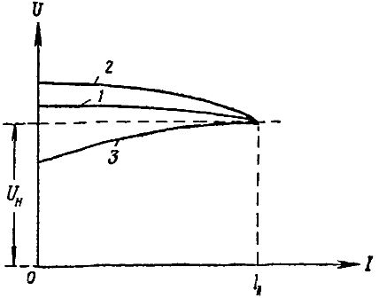
Rice. 3. External characteristics of the alternator for different loads: 1 — active, 2 — inductive, 3 capacitive
Control characteristic of a synchronous generator
The control characteristic of a synchronous generator expresses the dependence of the field current i in the generator on the load I with a constant effective value of the voltage at the terminals of the generator (U = const), a constant number of revolutions of the rotor of the generator per minute (n = const) and the constancy of the factor of the power (cos φ = const).
In fig.4 three control characteristics of a synchronous generator are given. Curve 1 refers to the active load case (because φ = 1).
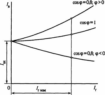
Rice. 4. Alternator control characteristics for different loads: 1 — active, 2 — inductive, 3 — capacitive
Here we see that as the load I on the generator increases, the excitation current increases. This is understandable, because with an increase in the load I, the voltage drop in the active resistance of the armature winding of the generator increases, and it is necessary to increase the electromotive force E of the generator by increasing the excitation current iv. To keep the voltage constant U .
Curve 2 refers to the case of an active-inductive load at cos φ = 0.8... This curve rises more steeply than curve 1, due to the demagnetization of the armature reaction, which reduces the magnitude of the electromotive force E and therefore the voltage U at the terminals of the generator.
Curve 3 refers to the case of an active-capacitive load at cos φ = 0.8. This curve shows that as the load on the generator increases, less excitation current i is required in the generator to maintain a constant voltage across its terminals. This is understandable, since in this case the armature reaction increases the main magnetic flux and therefore contributes to an increase in the electromotive force of the generator and the voltage at its terminals.