Oscillator - principle of operation, types, application
 An oscillating system is called an oscillator. That is, oscillators are systems in which some changing indicator or several indicators are periodically repeated. The same word "oscillator" comes from the Latin "oscillo" - swing.
Oscillators play an important role in physics and technology because almost any linear physical system can be described as an oscillator. Examples of the simplest oscillators are an oscillating circuit and a pendulum. Electrical oscillators convert direct current to alternating current and create oscillations at the required frequency using a control circuit.

Using the example of an oscillatory circuit consisting of a coil of inductance L and a capacitor of capacitance C, it is possible to describe the basic process of operation of an electrical oscillator. A charged capacitor, immediately after connecting its terminals to the coil, begins to discharge through it, while the energy of the electric field of the capacitor is gradually converted into the energy of the electromagnetic field of the coil.
When the capacitor is fully discharged, all of its energy will go into the energy of the coil, then the charge will continue to move through the coil and recharge the capacitor in the opposite polarity than it was to begin with.
Also, the capacitor will begin to discharge again through the coil, but in the opposite direction, etc. — each period of oscillation in the circuit, the process will repeat itself until the oscillations disappear due to the dissipation of energy on the resistance of the coil of wire and in the dielectric of the capacitor.
In one way or another, the oscillating circuit in this example is the simplest oscillator, since in it the following indicators periodically change: the charge in the capacitor, the potential difference between the plates of the capacitor, the strength of the electric field in the dielectric of the capacitor, the current through the coil and the magnetic induction of the coil. In this case, free damping oscillations occur.
In order for the oscillatory oscillations to become undamped, it is necessary to replenish the dissipated electrical energy. At the same time, in order to maintain a constant amplitude of oscillations in the circuit, it is necessary to control the incoming electricity so that the amplitude does not decrease below and does not increase above a given value. To achieve this goal, a feedback loop is introduced in the circuit.
In this way, the oscillator becomes a positive feedback amplifier circuit, where the output signal is partially fed to the active element of the control circuit, as a result of which continuous sinusoidal oscillations of constant amplitude and frequency are maintained in the circuit.That is, sinusoidal oscillators work due to the flow of energy from active elements to passive ones, with the support of the process from a feedback loop. The vibrations have a slightly variable shape.
The oscillators are:
-
with positive or negative feedback;
-
with sinusoidal, triangular, sawtooth, rectangular waveform; low frequency, radio frequency, high frequency, etc.;
-
RC, LC — oscillators, crystal oscillators (quartz);
-
constant, variable or adjustable frequency oscillators.
Oscillator (generator) Royer
To convert a constant voltage into rectangular pulses or to obtain electromagnetic oscillations for some other purpose, you can use a Royer transformer oscillator or a Royer generator... This device includes a pair of bipolar transistors VT1 and VT2, a pair of resistors R1 and R2, a pair of capacitors C1 and C2 as well saturated magnetic circuit with coils — transformer T.
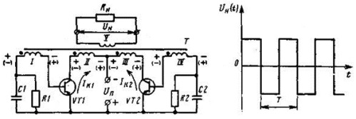
The transistors operate in key mode, and the saturated magnetic circuit allows positive feedback and, if necessary, galvanically isolates the secondary winding from the primary loop.
At the initial moment of time, when the power supply is turned on, small collector currents begin to flow through the transistors from the source Up. One of the transistors will open earlier (let VT1), and the magnetic flux crossing the windings will increase and the EMF induced in the windings will increase at the same time. The EMF in the base windings 1 and 4 will be such that the transistor which started to open first (VT1) will open and the transistor with a lower starting current (VT2) will close.
The collector current of the transistor VT1 and the magnetic flux in the magnetic circuit will continue to increase until the saturation of the magnetic circuit, and at the moment of saturation the EMF in the windings will turn to zero. The collector current VT1 will begin to decrease, the magnetic flux will decrease.
The polarity of the EMF induced in the windings will reverse and since the base windings are symmetrical, the transistor VT1 starts to close and VT2 starts to open.
The collector current of the transistor VT2 will begin to increase until the increase in magnetic flux stops (now in the opposite direction), and when the EMF in the windings returns to zero, the collector current VT2 begins to decrease, the magnetic flux decreases, the EMF changes polarity . Transistor VT2 will close, VT1 will open and the process will continue to repeat itself cyclically.
The frequency of oscillations of the Royer generator is related to the parameters of the power source and the characteristics of the magnetic circuit according to the following formula:
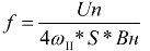
Up — supply voltage; ω is the number of turns of each coil of the collector; S is the cross-sectional area of the magnetic circuit in sq. Cm; Bn — core saturation induction.
Since in the process of saturation of the magnetic circuit, the EMF in the windings of the transformer will be constant, then in the presence of a secondary winding, with a load connected to it, the EMF will take the form of rectangular pulses. Resistors in the base circuits of the transistors stabilize the operation of the converter, and capacitors help to improve the shape of the output voltage.
Royer oscillators can operate at frequencies from units to hundreds of kilohertz, depending on the magnetic properties of the core in the T transformer.
Welding oscillators
To facilitate ignition of the welding arc and maintain its stability, welding oscillators are used. The welding oscillator is a high frequency surge generator designed to operate with conventional AC or DC power supplies…. It is a damped oscillation spark generator based on a LF step-up transformer with a secondary voltage of 2 to 3 kV.
In addition to the transformer, the circuit contains a limiter, an oscillating circuit, coupling coils and a blocking capacitor. Thanks to the oscillating circuit, as the main component, the high-frequency transformer works.
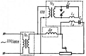
The high-frequency vibrations pass through the high-frequency transformer and the high-frequency voltage is applied through the arc gap. A bypass capacitor prevents the arcing power source from being bypassed. A choke is also included in the welding circuit for reliable isolation of the oscillator coil from HF currents.
With a power of up to 300 W, the welding oscillator gives pulses lasting several tens of microseconds, which is quite enough to ignite a light arc. High frequency, high voltage current is simply superimposed on the working welding circuit.
Oscillators for welding are of two types:
-
pulse power supply;
-
continuous action.
Continuous oscillator exciters operate continuously during the welding process, striking the arc by superimposing a high frequency (150 to 250 kHz) and high voltage (3000 to 6000 V) auxiliary current on top of its current.
This current will not harm the welder if safety precautions are followed. The arc under the influence of the high-frequency current burns evenly at a low value of the welding current.
The most efficient welding oscillators in series connection, as they do not require the installation of high voltage protection for the source. During operation, the arrester emits a quiet crackle through a gap of up to 2 mm, which is adjusted before starting work with a special screw (at this time, the plug is removed from the outlet!).
AC welding uses pulsed power oscillators to help ignite the arc while reversing the polarity of the AC current.