Current and voltage with parallel, series and mixed wiring
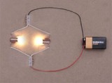 Real electrical circuits most often include not one wire, but several wires connected in some way to each other. In its simplest form electrical circuit there is only an "input" and an "output", that is, two outputs for connecting to other wires through which charge (current) has the ability to flow into the circuit and leave the circuit. At a steady current in the circuit, the input and output current values will be the same.
If you look at an electrical circuit that includes several different wires, and consider a pair of points (input and output) on it, then in principle the rest of the circuit can be thought of as a single resistor (in terms of its equivalent resistance).
With this approach, they say that if the current I is the current in the circuit, and the voltage U is the terminal voltage, that is, the difference in electric potentials between the "input" and "output" points, then the ratio U / I can be considered as the value of the equivalent resistance R circuit entirely.
If Ohm's Law is satisfied, the equivalent resistance can be calculated quite easily.
Current and voltage with series connection of wires
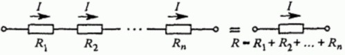
In the simplest case, when two or more conductors are connected together in a series circuit, the current in each conductor will be the same, and the voltage between the "output" and the "input", that is, at the terminals of the entire circuit, will be equal to the sum from the voltages in the resistors that make up the circuit. And since Ohm's law is valid for each of the resistors, we can write:
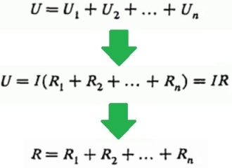
So, the following patterns are characteristic of the serial connection of wires:
-
To find the total resistance of the circuit, the resistances of the wires that make up the circuit are added;
-
The current through the circuit is equal to the current through each of the wires that make up the circuit;
-
The voltage across the terminals of a circuit is equal to the sum of the voltages in each of the wires that make up the circuit.
Current and voltage with parallel connection of wires
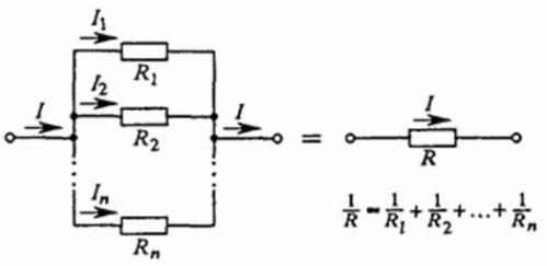
When several wires are connected in parallel with each other, the voltage at the terminals of such a circuit is the voltage of each of the wires that make up the circuit.
The voltages of all wires are equal to each other and equal to the applied voltage (U). The current through the entire circuit — at the "input" and "output" — is equal to the sum of the currents in each of the branches of the circuit, combined in parallel and making up this circuit. Knowing that I = U / R, we get that:
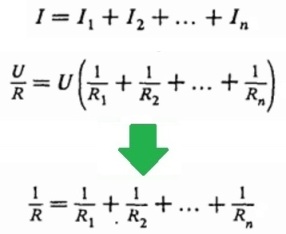
So, the following patterns are characteristic of the parallel connection of wires:
-
To find the total resistance of the circuit, add the reciprocals of the resistances of the wires which make up the circuit;
-
The current through the circuit is equal to the sum of the currents through each of the wires forming the circuit;
-
The voltage across the terminals of a circuit is equal to the voltage across each of the wires that make up the circuit.
Equivalent circuits of simple and complex (combined) circuits
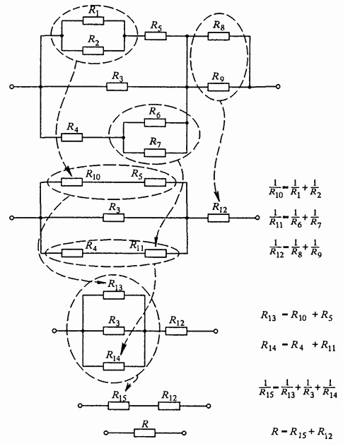
In most cases, electrical diagrams representing a combined connection of wires lend themselves to step-by-step simplification.
Groups of series-connected and parallel parts of the circuit are replaced by equivalent resistances according to the above principle, step by step calculating the equivalent resistances of the pieces, then bringing them to one equivalent value of the resistance of the whole circuit.
And if at first the circuit seems quite confusing, then, simplified step by step, it can be broken down into smaller circuits of series and parallel connected wires, and so in the end it is greatly simplified.
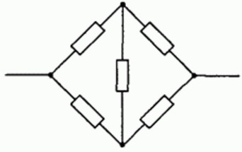
Meanwhile, not all schemes can be simplified in such a simple way. A seemingly simple "bridge" circuit of wires cannot be investigated in this way. A few rules should apply here:
-
For every resistor, Ohm's law is fulfilled;
-
At each node, that is, at the point of convergence of two or more currents, the algebraic sum of the currents is zero: the sum of the currents flowing into the node is equal to the sum of the currents flowing out of the node (Kirchhoff's first rule);
-
The sum of the voltages on the circuit sections when bypassing each path from «input» to «output» is equal to the voltage applied to the circuit (Kirchhoff's second law).
Bridge wires
To consider an example of using the above rules, we calculate a circuit assembled from wires combined in a bridge circuit. To make the calculations not too complicated, we will assume that some of the wire resistances are equal to each other.
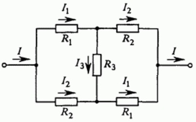
Let us denote the directions of currents I, I1, I2, I3 on the way from the "input" to the circuit — to the "output" of the circuit. It can be seen that the circuit is symmetrical, so the currents through the same resistors are the same, so we will denote them with the same symbols. In fact, if you change the «input» and «output» of the circuit, then the circuit will be indistinguishable from the original.
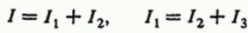
For each node you can write the current equations, based on the fact that the sum of the currents flowing into the node is equal to the sum of the currents flowing out of the node (the law of conservation of electric charge), you get two equations:
The next step is to write down the equations for the sums of the voltages for individual sections of the circuit as you go around the circuit from the input to the output in different ways. Since the circuit is symmetrical in this example, two equations are sufficient:

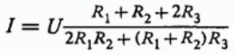
In the process of solving a system of linear equations, a formula is obtained for finding the magnitude of the current I between the "input" and "output" terminals, based on the specified voltage U applied to the circuit and the resistances of the wires:
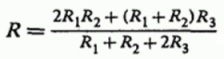
And for the total equivalent resistance of the circuit, based on the fact that R = U / I, the formula follows:
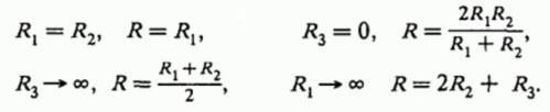
You can even check the correctness of the solution, for example, by leading to the limiting and special cases of the resistance values:
Now you know how to find current and voltage for parallel, series, mixed, and even connecting wires by applying Ohm's law and Kirchhoff's rules. These principles are very simple, and even the most complex electrical circuit with their help is ultimately reduced to an elementary form through a few simple mathematical operations.