How to construct a vector diagram of currents and voltages
Vector diagrams are a method of graphically calculating voltages and currents in AC circuits, where alternating voltages and currents are symbolically (conventionally) depicted using vectors.
The method is based on the fact that any quantity that changes according to a sinusoidal law (see — sinusoidal oscillations), can be defined as the projection onto a chosen direction of a vector rotating around its initial point with an angular velocity equal to the angular frequency of oscillation of the indicated variable.
Therefore, any alternating voltage (or alternating current) that varies according to a sinusoidal law can be represented by means of such a vector rotating with an angular velocity equal to the angular frequency of the displayed current, and the length of the vector in a certain scale represents the amplitude of the voltage, and the angle represents the initial phase of that voltage...
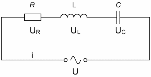
Considering electrical circuit, consisting of a series-connected AC source, a resistor, an inductance, and a capacitor, where U is the instantaneous value of the AC voltage, and i is the current at the current instant, and U varies according to the sinusoidal (cosine) law, then for the current we can we write:

According to the law of conservation of charge, the current in a circuit has the same value at all times. Therefore, the voltage will drop across each element: UR — across the active resistance, UC — across the capacitor, and UL — across the inductance. According to Kirchhoff's second rule, the source voltage will be equal to the sum of the voltage drops on the circuit elements, and we have the right to write:

notice this according to Ohm's law: I = U / R, and then U = I * R. For an active resistance, the value of R is determined exclusively by the properties of the conductor, it does not depend on either the current or the moment in time, therefore the current is in phase with the voltage and you can write:

But the capacitor in the AC circuit has a reactive capacitive resistance and the capacitor voltage always lags in phase with the current by Pi/2, then we write:

coil, inductive, in the alternating current circuit it acts as an inductive resistance of reactance, and the voltage on the coil at any time is ahead of the current in phase by Pi /2, therefore for the coil we write:

You can now write the sum of the voltage drops, but in general form for the voltage applied to the circuit, you can write:

It can be seen that there is some phase shift associated with the reactive component of the total resistance of the circuit when alternating current flows through it.
Since in alternating current circuits both current and voltage change according to the cosine law, and instantaneous values differ only in phase, physicists came up with the idea in mathematical calculations to consider currents and voltages in alternating current circuits as vectors, since trigonometric functions can be described by vectors. So, let's write the voltages as vectors:

Using the method of vector diagrams, it is possible to derive, for example, Ohm's law for a given series circuit under conditions of alternating current flowing through it.
According to the law of conservation of electric charge, at any instant of time the current in all parts of a given circuit is the same, so let's set aside the vectors of the currents, construct a vector diagram of the currents:

Let the current Im be plotted in the direction of the X-axis — the value of the amplitude of the current in the circuit. The voltage of the active resistance is in phase with the current, which means that these vectors will be jointly directed, we will postpone them from one point.
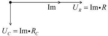
The voltage in the capacitor lags Pi / 2 of the current, therefore, we place it at right angles down, perpendicular to the voltage vector on the active resistance.
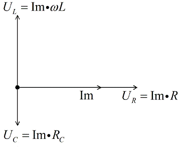
The coil voltage is in front of Pi/2 current, so we place it at right angles upwards, perpendicular to the voltage vector on the active resistance. Let's say for our example, UL > UC.
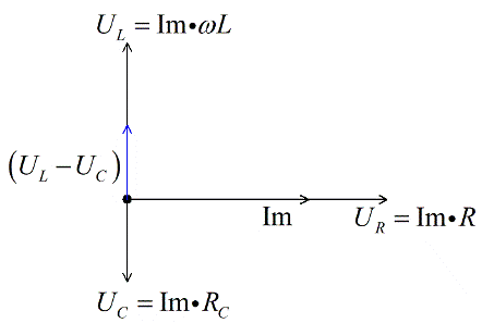
Since we are dealing with a vector equation, we add the stress vectors on the reactive elements and get the difference. For our example (we assumed UL > UC) it will point upwards.
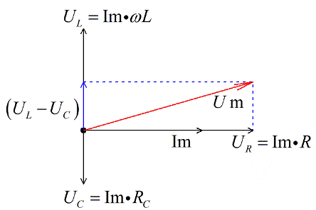
Now let's add the voltage vector to the active resistance and we get, according to the vector addition rule, the total voltage vector. Since we took the maximum values, we get the vector of the amplitude value of the total voltage.
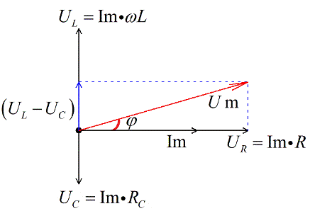
Since the current has changed according to the cosine law, the voltage has also changed according to the cosine law, but with a phase shift. There is a constant phase shift between current and voltage.
Let's record Ohm's Law for total resistance Z (impedance):

From vector images according to the Pythagorean theorem we can write:

After elementary transformations, we obtain an expression for the impedance Z of an alternating current circuit consisting of R, C and L:

Then we get an expression for Ohm's law for an AC circuit:
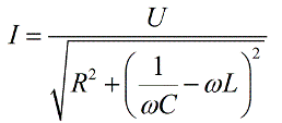
Note that the highest current value is obtained in the circuit of resonance under conditions where:

Cosine phi from our geometric constructions it turns out:

