Connection diagrams of three-phase circuits in electrical networks
The advantages of three-phase networks, ensuring their wide distribution, are obvious:
-
energy is transmitted over three wires over long distances more economically than if there were fewer phases;
-
synchronous generators, asynchronous motors, three-phase transformers — easy to manufacture, economical and reliable in operation;
-
Finally, a three-phase AC system has the ability to provide (and take) constant instantaneous power for a period of sinusoidal current if the three-phase generator load is the same in all phases.
Let's look at what basic three-phase circuits exist in electrical networks.
The windings of a three-phase alternator can generally be connected to loads in various ways. So, the most economical way would be to directly connect a separate load to each phase of the generator, extending two wires for each load. But with this approach, six wires will be needed to connect.
This is very wasteful in terms of material consumption and inconvenient.To achieve material savings, the windings of a three-phase generator are simply combined in a «star» or «delta» circuit. With this wiring solution, a maximum of 4 ("star with zero point" or "delta") or a minimum of 3 are obtained.
A three-phase generator is depicted on diagrams in the form of three windings located at angles of 120 ° to each other. If the connection of the windings of the generator is carried out according to the "star" scheme, then the terminals of the same name of the windings are connected to each other at one point (the so-called "zero point" of the generator). The zero point is marked with the letter «O», and the free terminals (phase terminals) of the windings are marked with the letters «A», «B» and «C».
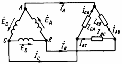
If the windings of the generator are connected to each other in a "triangle" scheme, then the end of the first winding is connected to the beginning of the second winding, the end of the second winding - to the beginning of the third, the end of the third - to the beginning of the first - the triangle is closed. Geometrically, the sum of the EMF in such a triangle will be zero. And if the load is not connected at all to the terminals «A», «B» and «C», the current will not flow through the windings of the generator.
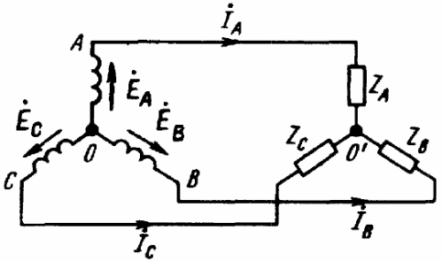
As a result, we get five basic schemes for connecting a three-phase generator with a three-phase load (see figures). In only three of these figures can you see a star-connected three-phase load, where the three ends of the load are combined at a single point. This point in the center of the load star is called «load zero point» and is marked «O'».
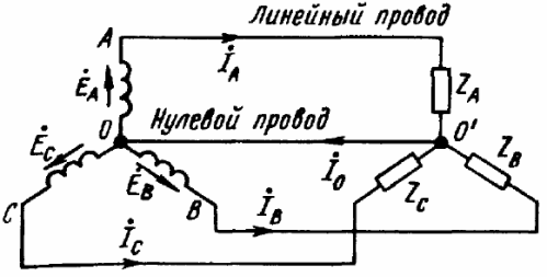
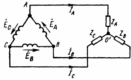
The conductor connecting the neutral points of the load and the generator is called the neutral conductor in such circuits. The current of the neutral wire is denoted as «Io».For the positive direction of the current, the direction from the load to the generator is usually taken, that is, from the point «O'» to the point «O».
The wires connecting the points "A", "B" and "C" of the generator terminals with the load are called line wires, and the circuits respectively: star-star with neutral wire, star-star, star-delta, delta- delta, delta-star - only five basic schemes for connecting three-phase circuits in electrical networks.
Currents flowing through linear conductors are called linear currents and denoted by Ia, Ib, Ic. For the positive direction of the line current, the direction from the generator to the load is usually taken. The module values of the line currents mean Il, as a rule, without additional indices, since it often happens that all the line currents of the circuit are equal in magnitude. The voltage between two linear conductors is the linear voltage, denoted by Uab, Ubc, Uca or, if we are talking about module, they simply write Ul.
Each of the generator windings is called a generator phase, and each of the three parts of a three-phase load is called a load phase. The currents of the phases of the generator and, accordingly, of the loads are called phase currents, denoted by If. The internal voltages of the generator phases and the load phases are called phase voltages, they are denoted Uf.
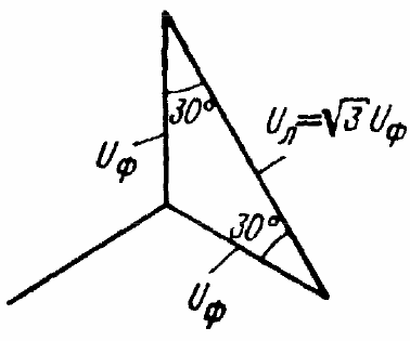
If the windings of the generator are connected in a «star», then the line voltages are 3 times the root (1.73 times) higher in absolute value than the phase voltages. This is because the line voltages will geometrically become the bases of isosceles triangles with acute angles at the base of 30°, where the legs are the phase voltages.Please note that a series of low three-phase voltages: 127, 220, 380, 660 — is simply formed by multiplying the previous value by 1.73.
When the windings of the generator are connected in "star", obviously the line current is equal to the phase current. But what happens to the voltages when the generator windings are delta connected? In this case, the network voltage will be equal to the phase voltage for each phase and for each part of the load: Ul = Uf. When the load is star-connected, the line current will be equal to the phase current: Il = If.
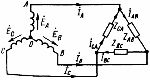
When the load is connected according to the "delta" scheme, for the positive direction of the currents, select the clockwise direction of the delta bypass. The determination is made by the relevant indices: from which point the current flows and to which point it flows, for example, Iab is the designation of the current from point "A" to point "B".
If a three-phase load is delta connected, then the line currents and phase currents will not be equal to each other. Line currents are then detected by phase currents according to Kirchhoff's first law: Ia = Iab-Ica, Ib = Ibc-Iab, Ic = Ica-Ibc.