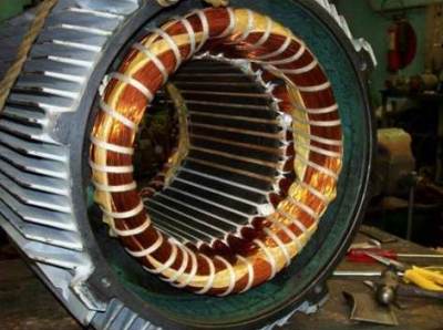
Stator windings of an induction motor
If you look at the stator winding of an induction motor, you will easily find that it is by no means just three single windings placed at 120 degrees to each other. For each of the phases of a three-phase winding, there are usually several sections. These sections vaguely resemble sections of the rotor winding of a commutator motor, but in an induction motor they perform completely different functions.
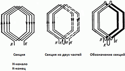
Check out the first picture. A section with four turns is shown here. Such a section occupies at least two stator slots. But the section can basically be split in half — now there are four channels. The two parts of the section will then need to be connected in series so that the EMF in them is summed.
Since the entire set of wires, isolated from each other in a section (or conventionally - in a part of a section), fits into one groove, it is possible to designate a bundle of wires in the diagram as one turn, even if there are several turns in a groove. The active conductors of each section can be laid in the grooves in one layer or in two layers, as on the rotor of a collector motor.
Suppose a three-phase induction motor has one pair of poles (2p = 2). Then, for each phase of the winding on each pole, a certain number of stator slots will fall: as a rule, from 1 to 5 (q). In the process of designing the machine, the most suitable value of this number q is selected. As a result, the total number of slots will be equal to — number of poles * number of phases * slots per phase pole (Z = 2pmq).
For example, there are: one pair of poles, three phases, two slots per phase pole. So, the total number of channels: Z = 2 * 3 * 2 = 12 channels. The figure below shows just such a winding, where there are 4 sections for each phase and each section consists of two parts (two windings per part) — each part is in the sphere of action of its pole (in two pole divisions tau, division on one pole — 180 degrees, all channels — 360 degrees).
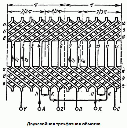
The slots are divided into phases like this: let the motor have two slots per pole per phase, then on the first pole division for phase A, slots 1 and 2 are accepted, and on the second pole division, 7 and 8, since Z / 2 = 6 and tau = 6 teeth.
The second phase (B) is offset from the first in space by 120 degrees or by 2/3 tau, that is, by 4 teeth, and therefore occupies channels 5 and 6 of the first pole division and channels 11 and 12 of the second pole division.
Finally, the third phase (C) is located in the remaining channels 8 and 9 of the second pole step and in channels 3 and 4 of the first pole step. Coil marking is always done on the outer layer of active wires.
As you already understood, to add the EMF of each phase, the sections inside the coils are connected in series, and the coils themselves (in opposite pole divisions) are connected oppositely: the end of the first is with the end of the second.
The stator windings are traditionally connected to a three-phase network according to one of two schemes: star or triangle… The triangle is for 220 volts, the star is for 380 volts.
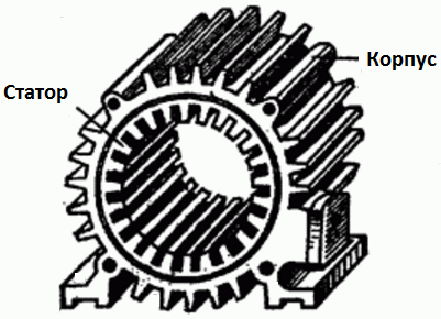
The figure shows the stator without a winding. The stator is installed in an aluminum, cast iron or steel motor housing by pressing the core inside. The core here consists of individual steel sheets, each of which is insulated with a special electrical varnish.
On the outside, the housing has fins, due to which the area of heat exchange with the surrounding air increases and the efficiency of active cooling increases — a plastic fan mounted on the rotor at the back (under the back cover with perforation) blows fins and thus cools the engine during operation , thus protecting the coils from overheating.