Three Phase Electric Circuits — History, Device, Characteristics of Voltage, Current and Power Calculations
A brief historical story
Historically, the first to describe the rotating magnetic field phenomenon Nikola Tesla, and the date of this discovery is considered to be October 12, 1887, the time when scientists filed patent applications related to induction motor and power transmission technology. On May 1, 1888, in the United States, Tesla would receive his main patents — for the invention of polyphase electric machines (including an asynchronous electric motor) and for systems for transmitting electrical energy by means of polyphase alternating current.
The essence of Tesla's innovative approach to this matter was his proposal to build the entire chain of generation, transmission, distribution and use of electricity as a single multiphase alternating current system, including generator, transmission line and alternating current motor, which Tesla then called "induction"...

On the European continent, parallel to Tesla's inventive activity, a similar problem was solved by Mikhail Osipovich Dolivo-Dobrovolsky, whose work was aimed at optimizing the method for large-scale use of electricity.
Based on the two-phase current technology of Nikola Tesla, Mikhail Osipovich independently developed a three-phase electrical system (as a special case of a multiphase system) and an asynchronous electric motor with a perfect design - with a «squirrel cage» rotor. Mikhail Osipovich would receive a patent for the engine on March 8, 1889 in Germany.
Three-phase network through Dolivo-Dobrovolski is built on the same principle as Tesla's: a three-phase generator converts mechanical energy into electrical, symmetrical EMF is fed to consumers through the power line, while the consumers are three-phase motors or single-phase loads (such as incandescent lamps).
Three-phase AC circuits are still used to provide the generation, transmission and distribution of electrical power. These circuits, as their name suggests, are made up of each of three electrical subcircuits, in each of which a sinusoidal EMF operates. These EMFs are generated from a common source, have equal amplitudes, equal frequencies, but are out of phase with each other by 120 degrees or 2/3 pi (one third of the period).
Each of the three circuits of a three-phase system is called a phase: the first phase - phase "A", the second phase - phase "B", the third phase - phase "C".
The beginning of these phases is indicated by the letters A, B and C, respectively, and the ends of the phases by X, Y and Z.These systems are economical compared to single phase; the possibility of simply obtaining a rotating magnetic field of the stator for the motor, the presence of two voltages to choose from - linear and phase.
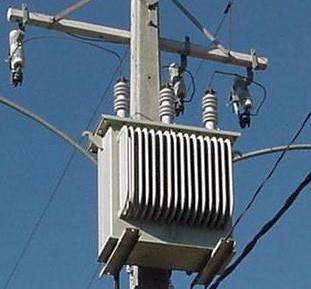
Three-phase generator and asynchronous motors

So, three-phase generator is a synchronous electrical machine designed to create three harmonic emfs 120 degrees out of phase (actually, in time) with respect to each other.
For this purpose, a three-phase winding is mounted on the stator of the generator, in which each phase consists of several windings, and the magnetic axis of each «phase» of the stator winding is physically rotated in space by a third of a circle relative to the other two «phases» .
This arrangement of the windings allows it to obtain a system of three-phase EMF during the rotation of the rotor. The rotor here is a permanent electromagnet excited by the current of the field coil located on it.
A turbine in a power plant rotates the rotor at a constant speed, the magnetic field of the rotor rotates with it, the magnetic field lines cross the wires of the stator windings, as a result, a system of induced sinusoidal EMF with the same frequency ( 50 Hz) is obtained, shifted one relative to another in time by a third of the period.
The amplitude of the EMF is determined by the induction of the magnetic field of the rotor and the number of turns in the stator winding, and the frequency is determined by the angular speed of rotation of the rotor. If we take the initial phase of the winding A equal to zero, then for a symmetrical three-phase EMF you can write in the form of trigonometric functions (phase in radians and degrees):
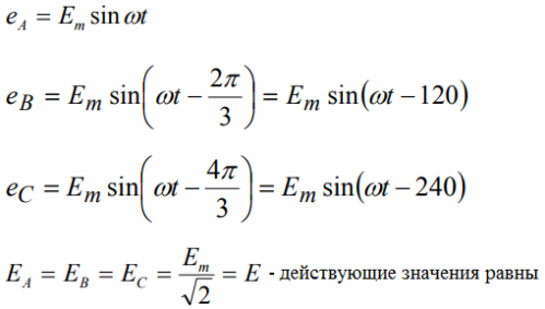
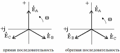
In addition, it is possible to record the effective values of the EMF in a complex form, as well as to display a set of instantaneous values in a graphical form (see Figure 2):
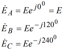
The vector diagrams reflect the mutual displacement of the phases of the three EMFs of the system, and depending on the direction of rotation of the rotor of the generator, the direction of rotation of the phase will differ (forward or backward). Accordingly, the direction of rotation of the rotor of an asynchronous motor connected to the network will be different:
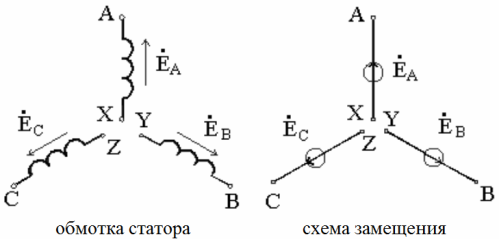
If there are no additional reserves, then the direct alternation of the EMF in the phases of a three-phase circuit is implied. The designation of the beginnings and ends of the generator windings — the corresponding phases, as well as the direction of the EMF acting in them, is shown in the figure (equivalent diagram on the right):
Schemes for connecting a three-phase load - "star" and "delta"
To supply the load through three wires of a three-phase network, each of the three phases is connected anyway according to the consumer or according to the phase of a three-phase consumer (the so-called Receiver of electricity).
A three-phase source can be represented by an equivalent circuit of three ideal sources of symmetrical harmonic EMF. Ideal receivers are represented here with three complex impedances Z, each fed by a corresponding phase of the source:
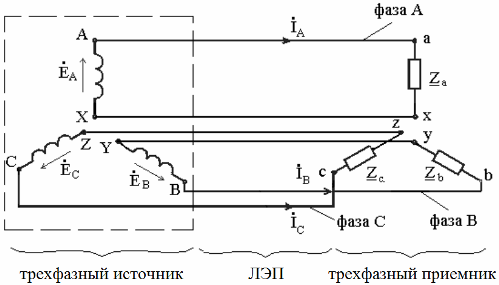
For clarity, the figure shows three circuits that are not electrically connected to each other, but in practice such a connection is not used. In reality, the three phases have electrical connections between them.
The phases of three-phase sources and three-phase consumers are connected to each other in different ways, and one of the two schemes - "delta" or "star" - is most often found.
The source phases and the consumer phases can be connected to each other in various combinations: the source is star-connected and the receiver is star-connected, or the source is star-connected and the receiver is delta-connected.
It is these combinations of compounds that are most often used in practice. The «star» scheme implies the presence of one common point in the three «phases» of the generator or transformer, such a common point is called the neutral of the source (or neutral of the receiver, if we talk about the «star» «of the consumer).
The wires connecting the source and the receiver are called line wires, they connect the terminals of the windings of the generator and receiver phases. The wire connecting the neutral of the source and the neutral of the receiver is called a neutral wire... Each phase forms a kind of individual electrical circuit, where each of the receivers is connected to its source by a pair of wires - one line and one neutral.
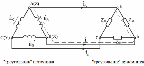
When the end of one phase of the source is connected to the beginning of its second phase, the end of the second to the beginning of the third, and the end of the third to the beginning of the first, this connection of the output phases is called a "triangle". Three receiving wires connected in a similar way to each other also form a «triangle» circuit, and the vertices of these triangles are connected to each other.
Each source phase in this circuit forms its own electrical circuit with the receiver, where the connection is formed by two wires. For such a connection, the names of the phases of the receiver are written with two letters in accordance with the wires: ab, ac, ca. The indices for the phase parameters are indicated by the same letters: complex resistances Zab, Zac, Zca.
Phase and line voltage
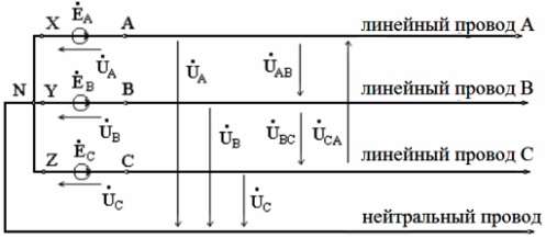
The source, the winding of which is connected according to the "star" scheme, has two systems of three-phase voltages: phase and line.
Phase voltage — between the line conductor and zero (between the end and the beginning of one of the phases).
Line voltage — between the beginning of the phases or between the line conductors. Here, the direction from the circuit point of higher potential to the point of lower potential is assumed to be the positive direction of the voltage.
Since the internal resistances of the generator windings are extremely small, they are usually neglected, and the phase voltages are considered to be equal to the phase of the EMF, therefore, on the vector diagrams, the voltage and EMF are denoted by the same vectors:
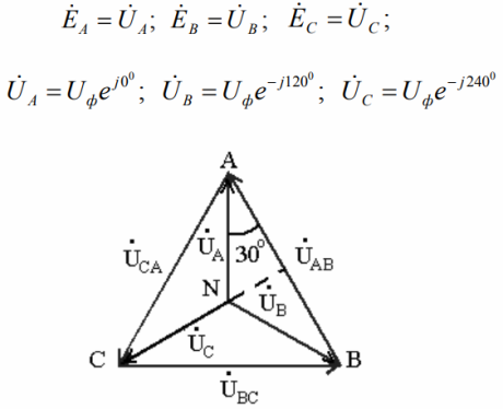
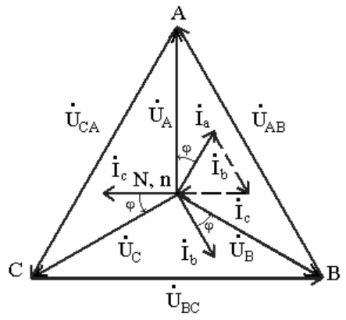
Taking the neutral point potential as zero, we find that the phase potentials will be identical to the source phase voltages and the line voltages to the phase voltage differences. The vector diagram will look like the picture above.
Each point on such a diagram corresponds to a particular point on a three-phase circuit, and the vector drawn between two points on the diagram will therefore indicate the voltage (its magnitude and phase) between the corresponding two points on the circuit for which the diagram is constructed.
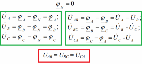
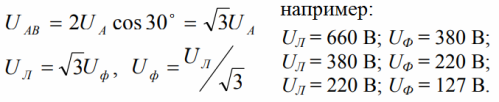
Due to the symmetry of the phase voltages, the line voltages are also symmetrical. This can be seen in the vector diagram. The line stress vectors only shift between 120 degrees. And the relationship between phase and line voltage is easily found from the triangle of the diagram: linear to the root of three times the phase.
By the way, for three-phase circuits, line voltages are always normalized, because only with the introduction of neutral will it be possible to talk about the phase voltage as well.
Calculations for the "star"
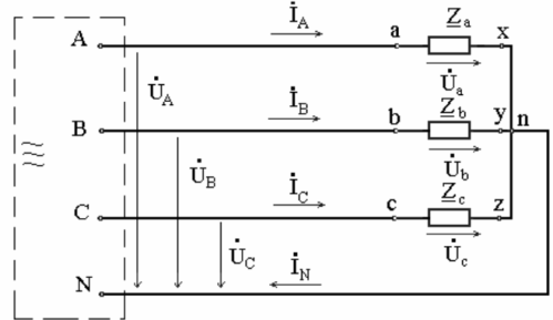
The figure below shows the equivalent circuit of the receiver, the phases of which are connected by a «star», connected through the conductors of the power line to a symmetrical source, the outputs of which are indicated by the corresponding letters. When calculating three-phase circuits, the tasks of finding line and phase currents are solved when the resistance of the receiver phases and the source voltage are known.
Currents in linear conductors are called linear currents, their positive direction — from the source to the receiver. The currents in the phases of the receiver are phase currents, their positive direction — from the beginning of the phase — to its end, like the direction of the EMF phase.
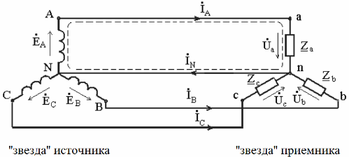
When the receiver is assembled in the "star" scheme, there is a current in the neutral wire, its positive direction is taken - from the receiver - to the source, as in the figure below.
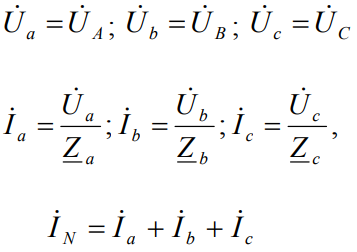
If we consider, for example, an asymmetrical four-wire load circuit, then the phase voltages of the sink, in the presence of a neutral wire, will be equal to the phase voltages of the source. Currents in each phase are according to Ohm's law... And Kirchhoff's first law will allow you to find the value of the current in the neutral (at the neutral point n in the figure above):
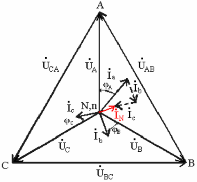
Next, consider the vector diagram of this circuit. It reflects the line and phase voltages, asymmetric phase currents are also plotted, shown in color and the current in the neutral wire. The neutral conductor current is plotted as the sum of the phase current vectors.
Now let the phase load be symmetrical and active-inductive in nature. Let's construct a vector diagram of currents and voltages, taking into account the fact that the current lags the voltage by an angle phi:
The current in the neutral wire will be zero. This means that when a balanced receiver is star-connected, the neutral wire has no effect and can generally be removed. No need for four wires, three is enough.
Neutral conductor in a three-phase current circuit
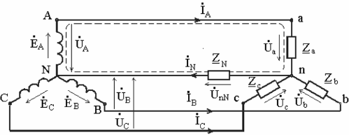
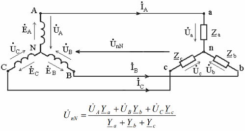
When the neutral wire is long enough, it offers appreciable resistance to the flow of current. We will reflect this in the diagram by adding a resistor Zn.
The current in the neutral wire creates a voltage drop across the resistance, which leads to voltage distortion in the phase resistances of the receiver. Kirchhoff's second law for phase circuit A leads us to the following equation, and then we find by analogy the voltages of phases B and C:
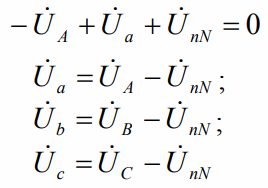
Although the source phases are symmetrical, the receiver phase voltages are unbalanced. And according to the method of nodal potentials, the voltage between the neutral points of the source and the receiver will be equal (EMF of the phases are equal to the phase voltages):
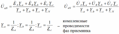
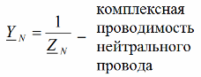
Sometimes, when the resistance of the neutral conductor is very small, its conductivity can be assumed to be infinite, which means that the voltage between the neutral points of a three-phase circuit is considered to be zero.
In this way, the symmetrical phase voltages of the receiver are not distorted. The current in each phase and the current in the neutral conductor are Ohm's law or according to Kirchhoff's first law:
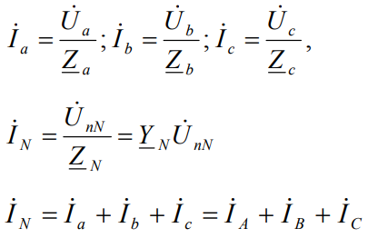
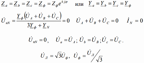
A balanced receiver has the same resistance in each of its phases.The voltage between the neutral points is zero, the sum of the phase voltages is zero and the current in the neutral conductor is zero.
Thus, for a star-connected balanced receiver, the presence of a neutral does not affect its operation. But the relationship between line and phase voltage remains valid:
An unbalanced star-connected receiver, in the absence of a neutral wire, will have a maximum neutral bias voltage (neutral conductance is zero, resistance is infinity):
In this case, the distortion of the receiver phase voltages is also maximum. The vector diagram of the phase voltages of the source with the construction of the neutral voltage reflects this fact:
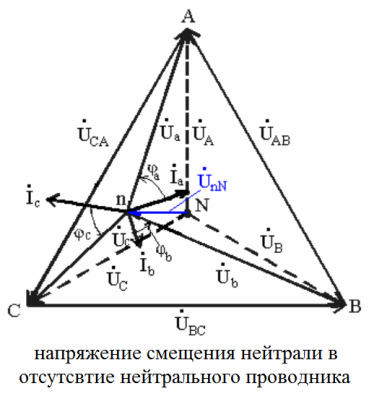
Obviously, with a change in the magnitude or nature of the resistances of the receiver, the value of the neutral bias voltage varies in the widest range, and the neutral point of the receiver on the vector diagram can be located in many different places. In this case, the phase voltages of the receiver will differ significantly.
Output: symmetrical load allows removal of the neutral wire without affecting the phase voltages of the receiver; Asymmetric loading by removing the neutral wire immediately results in the elimination of the hard coupling between the receiver voltages and the generator phase voltages — now only the generator line voltage affects the load voltages.
An unbalanced load leads to an unbalance of the phase voltages on it and to a displacement of the neutral point further from the center of the triangle of the vector diagram.
Therefore, the neutral conductor is necessary to equalize the phase voltages of the receiver in the conditions of its asymmetry or when it is connected to each of the phases of single-phase receivers designed for phase rather than line voltage.
For the same reason, it is impossible to install a fuse in the circuit of the neutral wire, since in the event of a break in the neutral wire at phase loads, there will be a tendency to dangerous overvoltages.
Calculations for the «triangle»
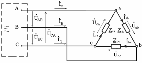
Now let's consider the connection of the phases of the receiver according to the "delta" scheme. The figure shows the source terminals and there is no neutral wire and nowhere to connect it. The task with such a connection scheme is usually to calculate the phase and line currents with known voltage source and load phase resistances.
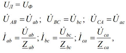
The voltages between the line conductors are the phase voltages when the load is delta connected. Except for the resistance of the line conductors, the voltages between the sources and the line are equated to the line-to-line voltages of the consumer phases. Phase currents are closed by complex load resistances and by wires.
For the positive direction of the phase current, the direction corresponding to the phase voltages is taken, from the beginning to the end of the phase, and for linear currents, from the source to the receiver. The currents in the load phases are found according to Ohm's law:
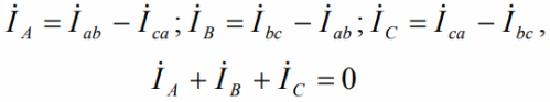
The peculiarity of the "triangle", unlike the star, is that the phase currents here are not equal to the linear ones. Phase currents can be used to calculate line currents using Kirchhoff's first law for nodes (for the vertices of a triangle).And adding the equations, we get that the sum of the complexes of line currents is equal to zero in the triangle, regardless of the symmetry or asymmetry of the load:
In a symmetrical load, the line (in this case equal to the phases) voltages create a system of symmetrical currents in the phases of the load. The phase currents are equal in magnitude, but differ only in phase by one-third of the period, that is, by 120 degrees. Line currents are also equal in magnitude, the differences are only in phases, which is reflected in the vector diagram:
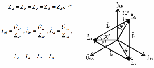
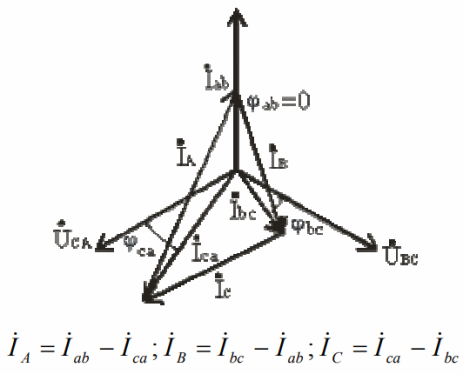
Suppose that the diagram is built for a symmetrical load of inductive nature, then the phase currents lag relative to the phase voltages by a certain angle phi. Line currents are formed by the difference of two phase currents (since the load connection is «delta») and are symmetrical at the same time.
After looking at the triangles in the diagram, we can easily see that the relationship between phase and line current is:
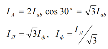
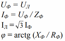
That is, with a symmetrical load connected according to the "delta" scheme, the effective value of the phase current is three times smaller than the effective value of the line current. Under the conditions of symmetry for the "triangle", the calculation for three phases reduces to the calculation for one phase. The line and phase voltages are equal to each other, the phase current is found according to Ohm's law, the line current is three times higher than the phase current.
An unbalanced load implies a difference in complex resistance, which is typical for feeding different single-phase receivers from the same three-phase network. Here the phase currents, phase angles, power in phases — will differ.
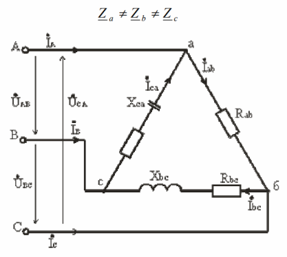
Let there be a purely active load (ab) in one phase, an active-inductive load (bc) in the other, and an active-capacitive load (ca) in the third. Then the vector diagram will look similar to the one in the figure:
The phase currents are not symmetrical and to find the line currents you will have to resort to graphical constructions or Kirchhoff's first law peak equations.
A distinctive feature of the «delta» receiver circuit is that when the resistance changes in one of the three phases, the conditions for the other two phases will not change, since the line voltages will not change in any way. Only the current in one specific phase and the currents in the transmission wires to which that load is connected will change.
In connection with this characteristic, the three-phase load connection scheme according to the «delta» scheme is usually sought for supplying an unbalanced load.
In the course of calculating an asymmetric load in the "delta" scheme, the first thing to do is to calculate the phase currents, then the phase shifts, and only then find the line currents in accordance with the equations according to Kirchhoff's first law or we resort to the vector diagram.
Three-phase power supply
A three-phase circuit, like any alternating current circuit, is characterized by total, active and reactive power. So, the active power for an unbalanced load is equal to the sum of three active components:

The reactive power is the sum of the reactive powers in each of the phases:

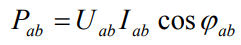
For the "triangle", the phase values are substituted, such as:
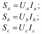
The apparent power of each of the three phases is calculated as follows:
Apparent power of each three-phase receiver:
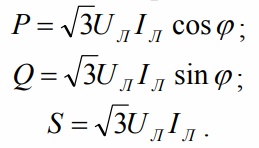
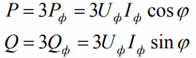
For a balanced three-phase receiver:
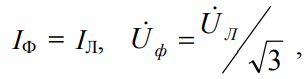
For a balanced star receiver:
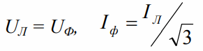
For a symmetrical "triangle":
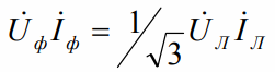
This means for both the "star" and the "triangle":
Active, Reactive, Apparent Powers — For each balanced receiver circuit: