Reversible single-phase motor
An induction motor is called a single-phase motor, on the stator of which there is only one working winding, directly fed by one phase of the network. There is also an auxiliary (starting) winding in a single-phase motor, which is used only at the time of starting the motor to give the rotor an initial impulse, in fact, the starting winding is turned on to take the rotor out of the equilibrium position, otherwise it will not to move without assistance and he will have to be pushed in some other way.
As with any motor, a single-phase motor also has a rotor that rotates and a stator that is stationary but only serves to create a time-varying magnetic field. The working and starting windings are located on the stator at right angles to each other, and the working winding occupies twice as many slots as the starting winding.
We can say that at the time of starting, such a motor works as a two-phase, and then switches to a single-phase mode of operation. The rotor of a single-phase asynchronous motor is the most common construction - squirrel cage (squirrel cage) or cylindrical (hollow).
What if there was no starter winding on the stator at all, or it was there but not used. In this case, when the motor is connected to the network, a pulsating magnetic field will appear in the working coil, and the rotor will fall under the conditions of a changing magnetic flux penetrating it.
But if the rotor is initially stationary and we suddenly apply an alternating current to the working coil only, then the rotor will not move from its place, because the total torque (clockwise and anti-clockwise) will be zero, despite the emf induced in the rotor. and there is no reason for rotation because Ampere's emergent forces cancel each other out.
It is a completely different matter, if the rotor is pushed, it will continue to rotate in the same direction as the initial push, because now, not only according to the law of electromagnetic induction, an EMF will be induced in the rotor and, accordingly, currents will arise, which according to the law of Amperes will be repelled by the magnetic field, but also (since the rotor already has rotation) the resulting torque in the direction of push will be greater than the torque against the direction of push. As a result, we get continued rotation of the rotor.
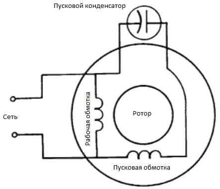
In order for the starting winding to push the rotor at the starting moment, it must not only be displaced in space relative to the working winding, but the current in it must also be shifted in phase with respect to the working winding current, then the combined action of these two stator windings will be equivalent not only to a pulsating magnetic field, but already to a rotating magnetic field. And this is exactly what is needed to accelerate the rotor during the start of a single-phase motor.
To phase-shift the current in the starting winding, a capacitor of the required capacitance is usually used, connected in series with the starting winding and creating a phase shift of 90 degrees. This is the standard solution for split phase motors.
As soon as the motor is connected to the network, the operator presses the switch button, which supplies energy to the coil start circuit, and as soon as the speed reaches the required value corresponding to the rating at the given frequency of the network, the button is released.
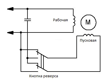
In order to obtain a reversal of a single-phase capacitor-start motor, it is sufficient to provide a condition where the starting pulse will be supplied in a direction other than the one originally supplied. This is achieved by changing the relative order of phase rotation in the working and starting windings.
To ensure these conditions, it is necessary to switch the working or starting coil, that is, to change the «polarity» of the connection of its terminals to the network or to the network and to the capacitor. This is easy to do because on a single phase motor there is a terminal block to which each of the ends of both the starting and running windings are brought out. The running coil has a lower active resistance than the starting coil, so it's easy to find with a multimeter. The best solution is to put the starter coil wires on a two-pole momentary switch.