Sensor connection diagrams
Connection diagrams of sensors, more commonly called measuring circuits, are designed to convert the output value of the sensor, and in most cases this is a change in their internal resistance, into a more convenient value for its subsequent use. As a rule, this is an electric current or change in voltage that can either be determined directly using an electrical measuring device or, after being amplified, fed to a suitable actuator or recording device.

For these purposes, the following switching schemes are widely used:
-
consistent,
-
pavement,
-
differential,
-
compensatory.
Sequential circuit diagram consists of a DC or AC source, the Rx sensor itself, a measuring device or direct drive mechanism, and usually an additional resistance Rd that limits the current in this circuit (Fig. 1). Such a switching circuit is most often widely used only with contact sensors for which Rx = 0 or Rx = ?.
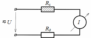
Rice. 1. Serial circuit for connecting sensors
Because when working with other sensors in the circuit of the measuring device, an electric current determined by the expression I = U /(Rx + Rd) always flows, and a slight change in the internal resistance of the sensor leads to a very small change in this current. As a result, the minimum section of the scale of the measuring device is used, and the accuracy of the measurement is practically reduced to zero. Therefore, for most other sensors, special measuring circuits are used, which significantly increase the sensitivity and accuracy of measurement.
Most commonly used bridge circuit switching, in which one and sometimes several sensors are connected in a certain way together with additional resistors in a quadrangle (the so-called Winston Bridge), which has two diagonals (Fig. 2). One of them, called a-b power diagonal, is designed to connect a DC or AC source, and the other, c-d measuring diagonal, includes a measuring device.
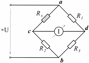
Rice. 2. Bridge circuit for connecting sensors
If the products of the resistance values of the opposite sides of the quadrilateral (bridge arms) are equal Rx x R3 = R1NS R2 the potentials of points c and d will be equal and there will be no current in the measurement diagonal. This state of the bridge circuit is commonly called bridge balance, i.e. the bridge circuit is balanced.
If the resistance of the Rx sensor changes due to external influence, then the balance will be disturbed and a current proportional to the change in this resistance will flow through the measuring device. In this case, the direction of this current indicates how the resistance of the sensor has changed (increased or decreased).Here, with an appropriate choice of the sensitivity of the measuring device, all of it working scale.
The bridge circuit under consideration is called unbalanced, as the measurement process takes place at imbalance bridge, i.e. imbalance. An unbalanced bridge circuit is most often used in cases where the resistance of the sensor under the influence of external forces can change very quickly per unit time, but then instead of a measuring device it is more expedient to use a recording device that will record these changes .
It is considered more sensitive balanced bridge circuit, in which a special measuring rheostat R (Fig. 3), equipped with a scale and called a rheochord in the measuring technique, is additionally connected to two adjacent arms.
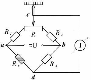
Rice. 3. Balanced bridge circuit
When working with such a circuit, with each change in the resistance of the sensor, the bridge circuit must be rebalanced with the included slider, i.e. while there is no current in the measuring diagonal. In this case, the value of the measured parameter (change in the resistance value of the sensor) is determined by a special scale that is equipped with this record and calibrated in units of the value measured by the sensor.
The higher accuracy of the balanced bridge is explained by the fact that it is easier to determine the lack of current in the measuring device than to directly measure its value, and balancing the bridge in such cases, as a rule, is carried out using a special electric motor controlled by the bridge circuit unbalance signal.
Bridge circuits for switching sensors are considered universal, since they can be powered by both direct and alternating current, and most importantly, several sensors can be connected to these circuits at the same time, which contributes to increasing no only the sensitivity, but also the measurement accuracy.
Differential circuit the inclusion of sensors is built using a special transformer powered by an alternating current network, the secondary winding of which is divided into two identical parts. Thus, in this circuit (Fig. 4) two adjacent circuits are formed, each of which has its own current loop I1 and I2. And the value of the current in the measuring device is determined by the difference of these currents, and if the resistances of the sensor Rx and the additional resistor Rd are equal, there will be no current in the measuring device.
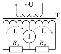
Rice. 4. Differential sensor switching circuit
When the resistance of the sensor changes, a current proportional to this change will flow through the measuring device, and the phase of this current will depend on the nature of the change in this resistance (increase or decrease). Only alternating current is used to power the differential circuit, and therefore it is more appropriate to use reactive sensors (inductive or capacitive) as sensors.
It is especially convenient to use such a switching circuit when working with differential inductive or capacitive sensors. When using such sensors, not only the magnitude of the movement, for example, of the ferromagnetic core (Fig. 5), but also the direction of this movement (its sign) is recorded, as a result of which the phase of the alternating current passing through the measuring device , changes.This further increases the sensitivity of the measurement.
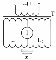
Rice. 5. Connection diagram of an inductive differential sensor
It should be noted that in order to increase the accuracy of the measurement, in some cases other types of similar measuring circuits are used, for example, balanced differential circuits… Such circuits include either a repeated chord or a special measurement autotransformer with a special scale, and the measurement process with such circuits is similar to measurements with a balanced bridge circuit.
Compensation scheme the inclusion of sensors is considered the most accurate of all those discussed above. Its operation is based on output voltage compensation or EMF. a sensor equal to it in terms of the voltage drop in the measuring rheostat (rheochord). Only a DC source is used to power the compensation circuit and it is mainly used with DC generator sensors.
Let's look at the operation of this circuit using the example of using a thermocouple as a sensor (Fig. 6).
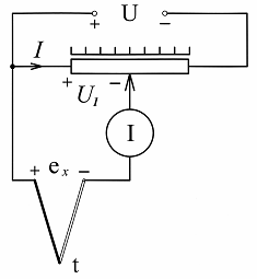
Rice. 6. Compensation circuit for switching on the thermoelectric sensor
Under the action of the applied voltage U, a current flows through the measuring rheostat, which causes a drop in the voltage U1 in the section of the rheostat from its left output to the motor. In case of equality of this voltage and EMF thermocouples — there will be no current through the glucometer.
If the value of the emf sensor changes, it is necessary to achieve the absence of this current again using the slider of the slider. Here, as in the equilibrium bridge circuit, the value of the measured parameter, in our case the temperature (emf thermocouple) is determined by the scale of the sliding wire, and the movement of its motor is carried out, most often, also with the help of a special electric motor.
The high accuracy of the compensation circuit is due to the fact that during the measurement, the electrical energy generated by the sensor is not consumed, since the current in the circuit of its inclusion is zero. This circuit can also be used with parametric sensors, but then an additional DC source is needed, which is used in the power supply circuit of the parametric sensor.